Other Parts Discussed in Thread: MSP-FET
Hello,
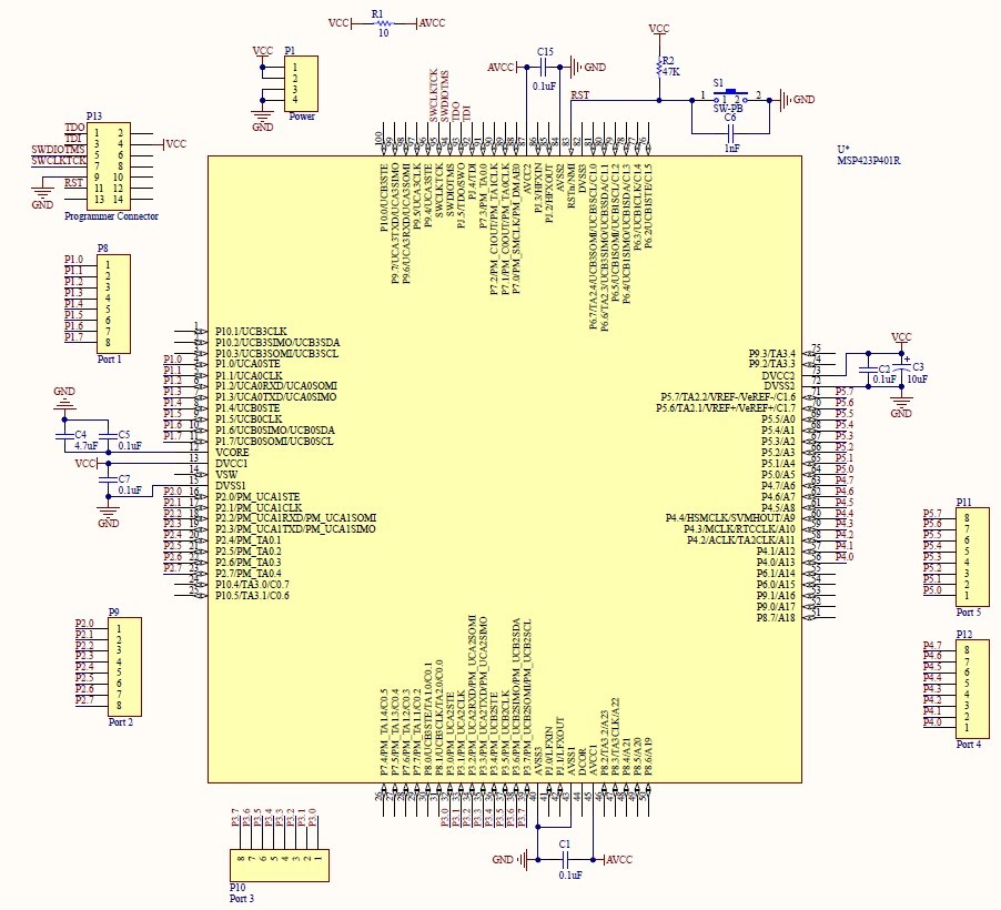
I'm making a custom development board for the MSP432P401R. I am using the MSP432 launchpad schematics as a reference when designing this. I have included my schematic below. I'm not using the low or high frequency external oscillators, so I'm just leaving the relevant pins disconnected. I just have a few questions before I start designing my PCB.
Are all of the DVCC pins "weighted" equally? Sorry if there is better terminology. What I mean is does it matter which pin I put my 10uF electrolytic capacitor (C3) next to? Or should I put it close to my "Power" header?
Currently, I don't have a 4.7uF capacitor (C4) on hand, but may be able to get one. If I'm not able to get one, can I use a larger electrolytic capacitor instead?
Also, is a 10-ohm resistor (R1) fine to connect VCC (3.3V) to AVCC? And does the 0.1uF (C15) cap create a low-pass filter to eliminate high-frequency noise from the analog reference?
And FYI, I'm using an MSP-FET programmer. That's why my programmer connector (P13) is setup the way it is.


