Part Number: MSP432P401R
Tool/software: Code Composer Studio
Hello TI community
I plan to use BMI160 IMU as motion sensor in my applcation. I have written the i2c write/read functions as follows (the MCU is MSP432P401R):
/************BMI160 I2C*********/
UCB1CTLW0 |= UCSWRST; // **Initialize USCI state machine**
P6SEL0 |= BIT4 + BIT5;
P6SEL1 &= ~(BIT4 + BIT5); // P6.4:SDA-P6.5:SCL
UCB1CTLW0 |= UCMST + UCMSB + UCSYNC + UCSSEL_2 + UCMODE_3; // I2C
UCB1BR0 = 12; // fSCL = SMCLK/12 = ~250kHz
UCB1BR1 = 0;
UCB1I2CSA = BMI160_I2C_ADDR; // Set slave address
UCB1CTLW0 &= ~UCSWRST; // **Initialize USCI state machine**
/*********************************************************************************/
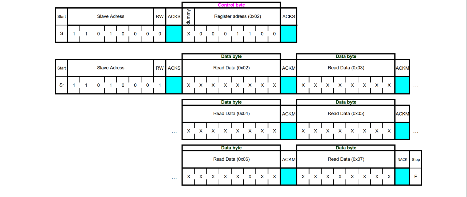
int8_t user_i2c_read(uint8_t dev_id, uint8_t reg_addr, uint8_t *reg_data, uint16_t len)
{
int8_t rslt = 0; /* Return 0 for Success, non-zero for failure */
/*
* The parameter dev_id can be used as a variable to store the I2C address of the device
*/
UCB1CTLW0 |= UCTR + UCTXSTT; // I2C TX, start condition
UCB1TXBUF = reg_addr; // Write reg_addr byte
UCB1CTLW0 |= UCTXSTP; // I2C stop condition after 1st TX
UCB1I2CSA |= BMI160_I2C_ADDR; // Set slave address
UCB1CTLW0 &=~UCA10; //10BIT ADDRESS
UCB1CTLW0 &=~UCTR;//CLEAR TRANSMIT MODE
UCB1CTLW0 |= UCTXSTT; // I2C RX, start condition
int i=0;
for (i=0;i<len;i++)
{
reg_data[i]=UCB1RXBUF;
}
UCB1CTLW0 |= UCTXSTP; // I2C stop condition after 1st TX
return rslt;
}
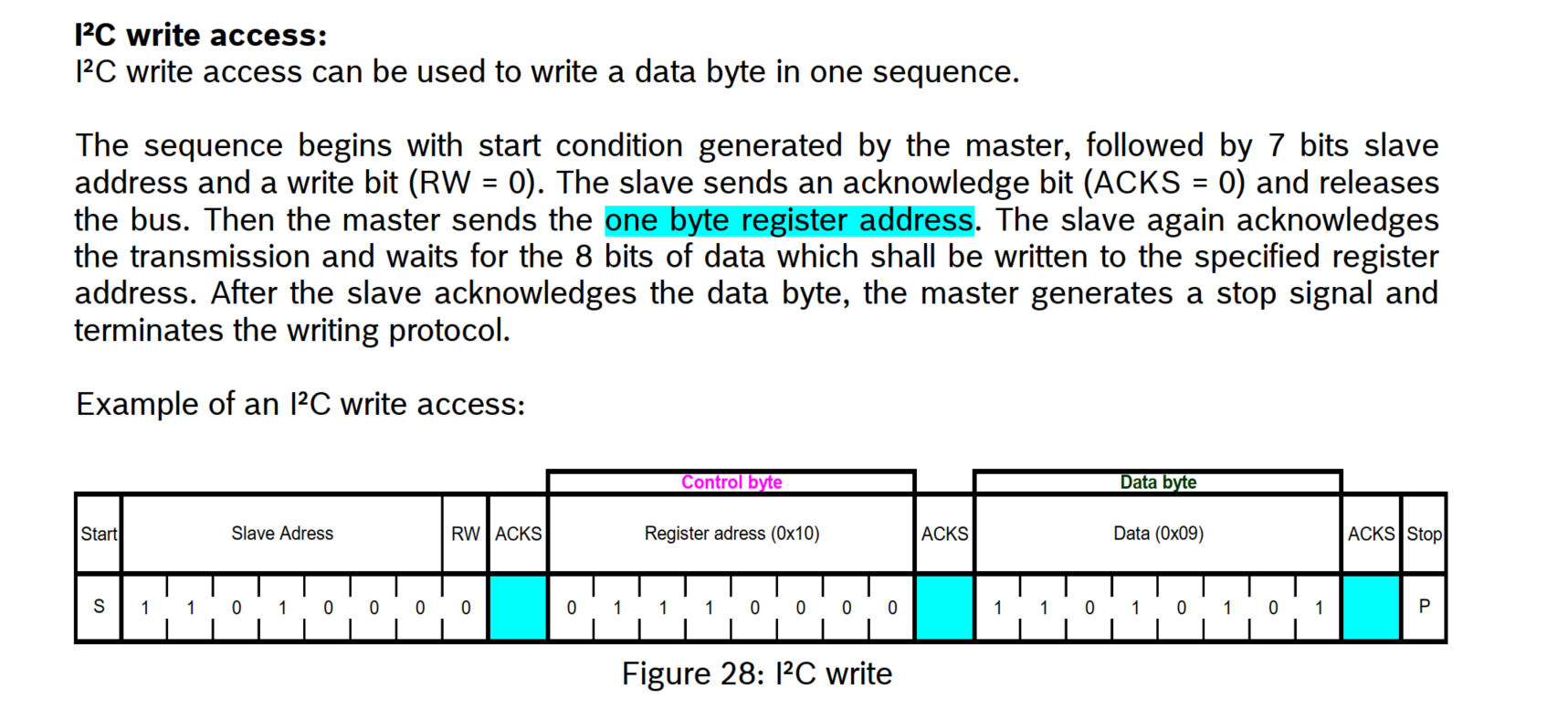
int8_t user_i2c_write(uint8_t dev_id, uint8_t reg_addr, uint8_t *reg_data, uint16_t len)
{
int8_t rslt = 0; /* Return 0 for Success, non-zero for failure */
UCB1CTLW0 |= UCTR + UCTXSTT; // I2C TX, start condition
UCB1TXBUF = reg_addr; // Write reg_addr byte
int i=0;
for (i=0;i<len;i++)
{
UCB1TXBUF=reg_data[i];
}
UCB1CTLW0 |= UCTXSTP; // I2C stop condition after 1st TX
return rslt;
}
is it the correct form read/write functions for interfacing with bmi160?
Thanks
Saber