This thread has been locked.

If you have a related question, please click the "Ask a related question" button in the top right corner. The newly created question will be automatically linked to this question.

How to calibrate Meter by Communication Protocol Spec of EMDC

Part Number: MSP430F6779
Other Parts Discussed in Thread: MSP-EXP430F5529LP, MSP-ISO

I have download the The Energy Measurement Design Center (EMDC) ( http://www.ti.com/tool/MSP-EM-DESIGN-CENTER )  and already generate code then flash to MCU. but I don't have MSP430F5529 for HID. so how to calibrate meter by Communication Protocol Spec,  how to calculation the calibration value? (don't use EMDC GUI software)

http://software-dl.ti.com/msp430/msp430_public_sw/mcu/msp430/EnergyMeasurementDesignCenter/1_30_00_00/release/EnergyMeasurementDesignCenter_1_30_00_00/docs/users_guide/html/Energy_Measurement_Technology_Guide_html/markdown/ch_comm_protocol.html

this have only protocol spec but don't show how to calibrate and setting

  • Hello,

    I am doing some research and will get back to you shortly with some information.

  • Hello,

    Thanks for your patience. For your development, I would highly recommend purchasing the MSP-EXP430F5529LP to use it as the HID bridge. This way, you can get familiar with the calibration method and monitor the communication. You can see the overall calibration communication flow in Figure 130 in the Communication Protocol Spec section in the EMDC Technology Guide. The existing calibration factors for gain and phase are modified based on what's measured.

    The sets of calibration factors depends on the number of phases in your EMDC design (e.g. 3 sets for 3 phases). After importing your EMDC-generated project into CCS, you can find the calibration factors in the 'EM_userConfig.c' file located in the <CCS project name>/EM_Config folder.

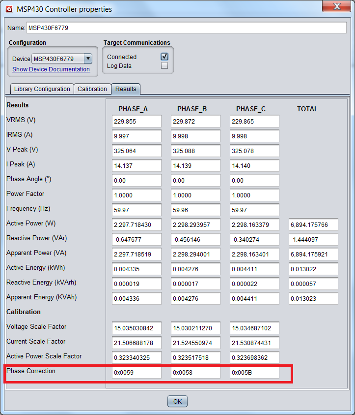
    As an example, here are the calibration factors for a single-phase MSP430i2041-based EMDC project. As you can see, the voltage and current results from the ADC channels need to be scaled from register values to human-understandable values (e.g VRMS). The scaling factors use IQ factors to achieve high accuracy without using floats. This also applies to the active and reactive power scaling factors. The GUI automatically calculates the error from what's measured versus what's expected and adjusts the values in the parenthesis accordingly. For phase correction, the hex value is adjusted which changes the preload delays on the ADCs. If you make any changes to these values in the code, be sure to recompile.

    EM_Phase_Calibration g_emPhaseCalibration[EM_PHASE_LENGTH] =
    {
        //PHASE_A
        {
            .voltageSF = _IQ24(23.722801983),
            .currentSF = _IQ24(16.265101492),
            .activePowerSF = _IQ30(0.385843045),
            .reactivePowerSF = _IQ30(0.385843045),
            .phaseCorrection = 0x0072,
        },
    };

    The EMDC GUI was intended to make difficult system calibration easy. We recommend that you have a custom project based on the EMDC code with your application code and then another default project with EMDC-generated code strictly for calibration to obtain the calibration factors, then update the factors in your custom project.

    I hope this helps.

    Regards,

    James

  • Part Number: MSP430F6779

    Tool/software: Code Composer Studio

    I can't using EMDC for Calibration because I can't using HID Bridge and must use the method of editing the source code following https://e2e.ti.com/support/microcontrollers/msp430/f/166/t/852414

    but I don't understand about detail for changing value especially in the part of phase shift and energy. I was finding in technical manual but don't found. Please answer the technical details for calibration.

    Best Regard

  • I understood all of those factor except .phaseCorrection could you explain how to calculate this value?

    For example

    if I supply 230V 5A PF1 Wh error is 0% and if supply 230V 5A PF0.5 I get error Wh is 1% how to calculate the .phaseCorrection ?

  • Hello,

    The .phaseCorrection contains the whole sample delays and fractional sample delays (ADC preload). In 'hal_adc.', you can see where the whole samples are gotten from .phaseCorrection by shifting the value to the right by 10.

    I would highly recommend purchasing the MSP-EXP430F5529 and MSP-ISO and use them with the GUI. I understand that you can't use the F5529 as the HID bridge in your design, but it allows you to see how the EMDC GUI (host) interacts with the target MSP430 during calibration. Using a logic analyzer, you can easily monitor the communication. The intent of the EMDC GUI was to make the calibration easier. After calibration, you can update the factors in Flash through the GUI or directly in the code.

    Regards,

    James

  • Understood what you said. but in the mass production we will not use EMDC GUI software, event we buy  MSP-EXP430F5529 and MSP-ISO we still don't know how to calculate the Phase correction ( .phaseCorrection) in the EMDC GUI software.

    Could you please show me how to calculate the Phase Correction in EMDC gui follow the Wh error, eg. 230V 5A PF0.5 I get error Wh is 1% what value we should setting to the Phase Correction ?.

  • Hello,

    The EMDC GUI can be used during production. You would load the EMDC-generated code onto the device, connect to the GUI, perform the calibration, save the calibration factors to INFO memory, and then program your code on the device. Assuming it's configured to pull the calibration factors from INFO, it would be calibrated. This was one of the goals of the GUI since calibration is one of the hardest tasks and it's not easily described nor implemented especially in a scalable and robust way. However, I understand your request and will do my best to shed some light on the process.

    I'll need a few days to look into this. Unfortunately, I'll be out tomorrow returning on Thursday. I should have something by Friday.

    Regards,

    James

  • Thanks for your support.

    Now we already figure out, we calculate the error of energy and then convert to Power factor error, then convert to Angle error, offset with the phaseCorrection (SD24BPREx), cal Delay resolution follow ref design (tidu817 page 16 and User guide SLAU208Q page 774).

**Attention** This is a public forum