Other Parts Discussed in Thread: MSP430WARE, , EVM430-FR6043, TDC1000, TDC7200, CAPTIVATE-PGMR
Tool/software: Code Composer Studio
Hello,
I've created a custom board with MSP430FR6043. I've used the "EVM430-FR6043" as an example. Now I'm using "USSSWLib_template_example" from "msp430ware_3_80_10_09" and I'm wondering how does the switching between transducers is operated. Do I have to switch the transducers between transactions by myself, or can it be done in the library (and how can I achieve this)?
Also I've been working with TDC1000 and TDC7200, and I understand why I get signals like this:
1.yellow- send signals
2.green - receive signal

But when I'm using the MSP, I'm getting different signals, like this:
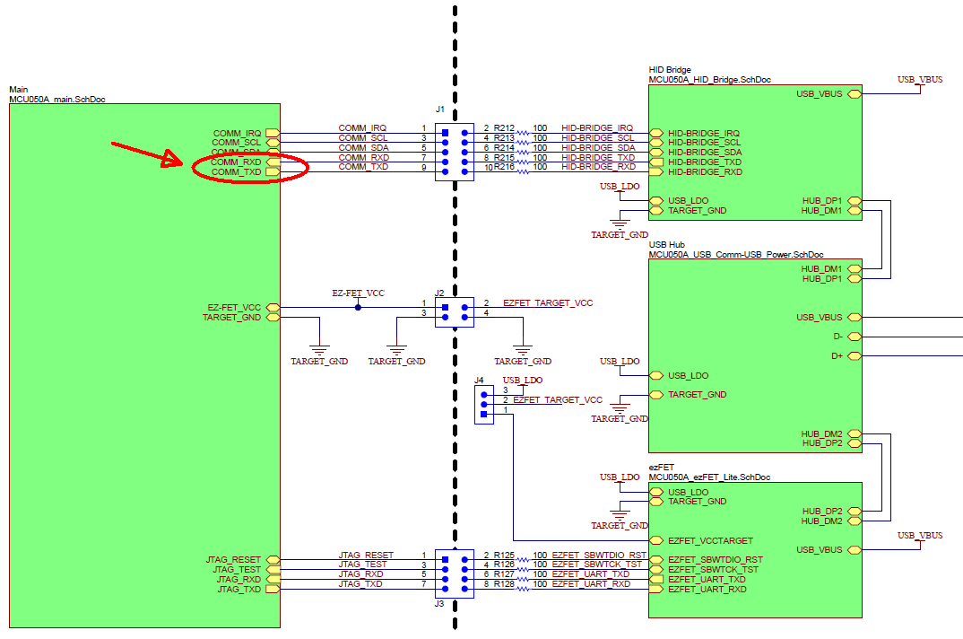
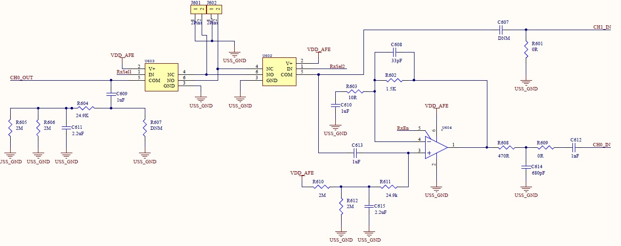
- yellow - J601
- green - J602
1.Two signals

2. Signals on the left
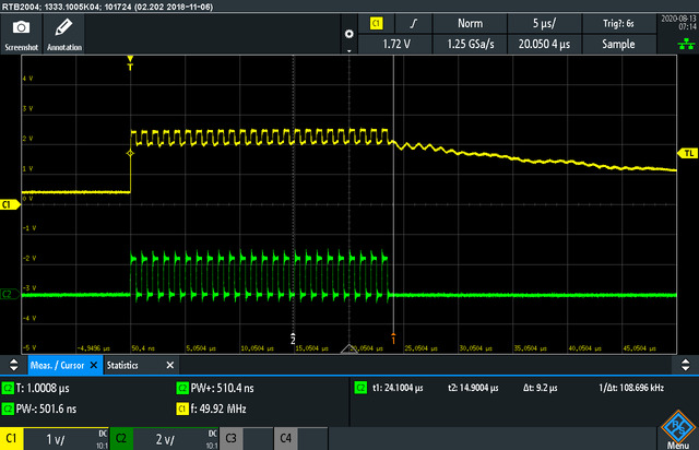
3.Signals on the right
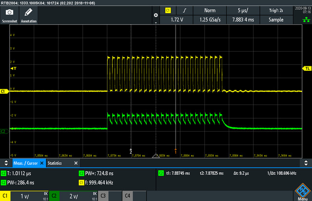
The pictures were taken when I didn't have the CH1_IN, CH0_IN and the transducers weren't connected to MSP, so I don't understand where the second signal is coming from.
Questions:
- According to my first paragraph, what do I have to do to switch the transducers?
- Where the second signal is coming from, if I don't have the transducers connected?