Other Parts Discussed in Thread: TMS570LC4357, HALCOGEN
Hi,
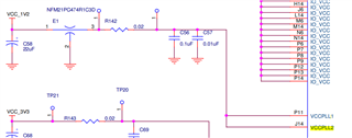
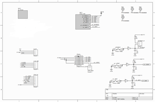
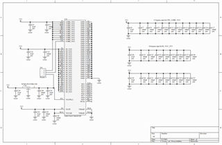
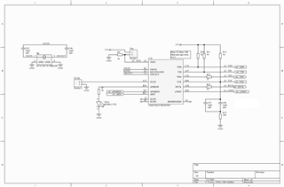
We are currently working on a custom board, and we are having a issue while programming the board using the XDS200.
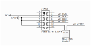
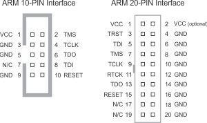
We are able to load a program on the development board using the cJTAG 4 pin method, that we are also using on our custom board.
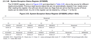
It seems like it we are able to connect to the target and run the current memory code by going in the debug mode (target -> Launch selected configuration -> connect to target), however the the PC is always going on the address 0x00000004.
I tried to change the memory by going into Tools->Memory fill, and I trying to change at the memory 0x00000000, but I got a memory writing error ("memory map preventing writing")
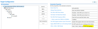
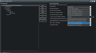
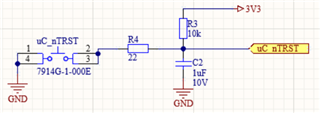
We check all the resets, they are in High state (3.3V), and the power lines are well connected. The test pin is also connected to GND. The JTAG test routine in the target configuration is working fine, and is not producing any error.
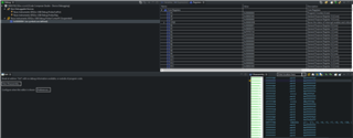
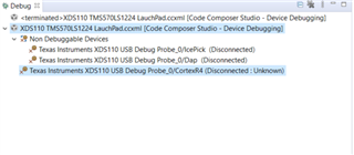
Here are the errors displayed while trying to load a program:
CortexR5: Can't Run Target CPU: (Error -242 @ 0x0) A router subpath could not be accessed. The board configuration file is probably incorrect. (Emulation package 9.3.0.00042)
CortexR5: Trouble Halting Target CPU: (Error -2064 @ 0x0) Unable to read device status. Reset the device, and retry the operation. If error persists, confirm configuration, power-cycle the board, and/or try more reliable JTAG settings (e.g. lower TCLK). (Emulation package 9.3.0.00042)
CortexR5: Error: (Error -1170 @ 0x0) Unable to access the DAP. Reset the device, and retry the operation. If error persists, confirm configuration, power-cycle the board, and/or try more reliable JTAG settings (e.g. lower TCLK). (Emulation package 9.3.0.00042)
CortexR5: Trouble Halting Target CPU: (Error -2064 @ 0x0) Unable to read device status. Reset the device, and retry the operation. If error persists, confirm configuration, power-cycle the board, and/or try more reliable JTAG settings (e.g. lower TCLK). (Emulation package 9.3.0.00042)
CortexR5: Unable to determine target status after 20 attempts
CortexR5: Failed to remove the debug state from the target before disconnecting.  There may still be breakpoint op-codes embedded in program memory.  It is recommended that you reset the emulator before you connect and reload your program before you continue debugging
CortexR5: File Loader: Memory write failed: Could not read 0x080002F4: target is not connected
It would be awesome is you had an idea of the possible errors that could make it happen, because we did not manage to identify what could be the possible issue.
Thank you very much !