This thread has been locked.

If you have a related question, please click the "Ask a related question" button in the top right corner. The newly created question will be automatically linked to this question.

TM4C1294KCPDT: GPTM re-load INT priority strays

Guru 55913 points
Part Number: TM4C1294KCPDT

Hello friends,

Configure GPTM3 full wide for Oneshot interrupt timeout event and reload 1 second value inside interrupt handler cycles.

GPTM3 CLK source: 16MHz PIOSC (65.5ns) 

Load value: 0xF42400 (16,000,000 * 65.5ns = 1 second one shot interval)

The problem is one shot period measured via scope probe GPIO port (1sec) intervals are stable until PWM0 is active. The one shot load time interrupt starts to widen >1.1 seconds (>100ms), seemingly depending on how often PWM0 is being interrupted for duty cycle updates. Why would the load value not hold the interrupt period fairly consistent to/with the down count time out expiration? It seems to be some kind of odd errata in the down count timer load value expiration and triggering the vectored interrupt handler.  The Oneshot is enabled inside an edge count timers CCP interrupt event. We don't really care how often the edge count interrupt occurs in this scenario. Yet don't believe the Oneshot should ever allow or process count reloads until the previous count expires.  

Is it not unreasonable to expect reload period drifts <16.6ns (<2 x SYSCLK (8.3ns)) NVIC running 120MHz? Is there a work around to have exact 1 second time interval not be impacted by other interrupt sources? The drifting interrupt handler (>100ms) stray even wider when GPTM clock 120MHz. Is it better to re-load the one shot load value outside the handler of the INT vector call-ed/er? Something odd is occurring to have Oneshot interval stray >100ms in the reload value grow uncontained in the process.   


  • Hello BP101,

    Have you checked the priorities for your interrupts for the timer vs the PWM? If the PWM has a higher priority, then the timer would be stuck waiting for PWM interrupts to resolve and the behavior you are seeing would make perfect sense. It is a single core MCU after all, so if the PWM has a higher priority, the timer may not be able to execute at the exact 1 second interval due to the PWM.

  • Hi Ralph,

    Ralph Jacobi said:
    , then the timer would be stuck waiting for PWM interrupts to resolve and the behavior you are seeing would make perfect sense

    Again >100ms gain in GPTM load interval should never result when NVIC is running 8.3ns, same as the CPU core speed. It has to be some other issue! It ain't 100ns gain it's >100ms locked to PWM0 interrupt speed. All NVIC pends have to share CPU time any single peripheral can't Bogart the priority slice, especially with NVIC tail chaining. You must realize 100ms is like the grand canyon wide when it comes to NVIC tail chaining INT pends. PWM0 zero count interrupt and ADC load count triggers are edge pulse generated interrupts.

    Perhaps AHB bus arbitration is not being considered or the GPTM reload interval simply grows as it should not ever exceed >100ms trap to interrupt. Interrupt timing around AHB arbitration is key but we have no idea how or if it even affects lower NVIC priority or GPTM reload values. Logically NVIC should never have real time clock attributes directly imposed upon any single peripheral. My opinion that includes perceived100ms GPTM unwarranted interval load value growth. It seems the load value grows as the NVIC priority interaction has not been elaborated to cause any such GPTM behavior.  

    Interrupt (IRQ). An interrupt, or IRQ, is an exception signaled by a peripheral or generated by a software request and fed through the NVIC (prioritized). All interrupts are asynchronous to instruction execution. In the system, peripherals use interrupts to communicate with the processor. Table 2-9 on page 116 lists the interrupts on the TM4C1294KCPDT controller.

    3.1.2.1 Level-Sensitive and Pulse Interrupts

    The processor supports both level-sensitive and pulse interrupts. Pulse interrupts are also described as edge-triggered interrupts. A level-sensitive interrupt is held asserted until the peripheral deasserts the interrupt signal. Typically this happens because the ISR accesses the peripheral, causing it to clear the interrupt request. A pulse interrupt is an interrupt signal sampled synchronously on the rising edge of the processor clock. To ensure the NVIC detects the interrupt, the peripheral must assert the interrupt signal for at least one clock cycle, during which the NVIC detects the pulse and latches the interrupt. When the processor enters the ISR, it automatically removes the pending state from the interrupt (see “Hardware and Software Control of Interrupts” on page 136 for more information). For a level-sensitive interrupt, if the signal is not deasserted before the processor returns from the ISR, the interrupt becomes pending again, and the processor must execute its ISR again. As a result, the peripheral can hold the interrupt signal asserted until it no longer needs servicing.

  • Nope as there are several other priorities groupings and other context enabling GPTM Oneshot timer remain constant, <100ns stray within 80us PWM interrupt window.

    Enabling TM3A Oneshot within context of CCP-0B edge triggered interrupt strays/delays TM3A load updates from interrupt handler context outside NVIC priority grouping synchronized timers. It appears TM3 load count update is neither immediate or occurring on the next timeout event. What ever update mode bits Tivaware is setting for Oneshot GPTM is not obvious from the caller syntax below. Note the PWM interrupts were being left enabled in all Tivaware GPTM configurations and we don't require any added mayhem. Also the unknown Tivaware TAMR TAILD bit 8 setting may add unexpected mayhem. Tivaware TimerConfiure() text makes no attempt to explain how anyone could OR a control define of the TAILD bit field control functions. What if the next cycle is delayed how does TAILD bit enter into the load interval inside interrupts handler of TM3A?

    MAP_IntPriorityGroupingSet(4);
    
     MAP_IntPrioritySet(INT_TIMER3A, 0x40); //Fan OneShot Taco Tick 
     MAP_IntPrioritySet(INT_TIMER0B,  0x40); //Fan Taco Edge Counter
     MAP_IntPrioritySet(INT_PWM0_0, 0x20); //PWM Gen Load
    
         /*****************************************************
         * GPTM-3: 32 bitwide Oneshot down timer configuration
         * for generating 60Hz fan Taco Tick intervals.
         *****************************************************/
        /* Set GPTM-3A clock source 120MHz or 16Mhz */
        MAP_TimerClockSourceSet(TIMER3_BASE, TIMER_CLOCK_PIOSC);
        /* Set GPTM-3A for OneShot next timeout.  */
        MAP_TimerConfigure(TIMER3_BASE, TIMER_CFG_ONE_SHOT);
    
       /* Timer loads TAILR after next timeout. */
        HWREG(TIMER3_BASE + TIMER_O_TAMR) |= TIMER_TAMR_TAILD;
    
        /* Load GPTM3A PIOSC:60Hz/16.6ms(0xF42400) */
        MAP_TimerLoadSet(TIMER3_BASE, TIMER_A,  0xF42400);
        /* Enable interrupt to occur on timer timeout.  */
        MAP_TimerIntEnable(TIMER3_BASE, TIMER_TIMA_TIMEOUT);
        /* Enable 220Hz/30Hz oneshot tick count for edge INT cycles */
        MAP_TimerEnable(TIMER3_BASE, TIMER_A);
        /* Register the global interrupt in the controller */
        TimerIntRegister(TIMER3_BASE, TIMER_A, FanSpeedTickHandler);
        MAP_IntEnable(INT_TIMER3A); 
    
        /* Synchronize CCP1 and 60 hertz tick timers
         * arresting clock drift between the two counters.
         * GPTM-3A: Oneshot no timeout action. GPTM-0B:
         * down edge count ILR=count value on timeout action */
        MAP_TimerSynchronize(TIMER0_BASE, TIMER_0B_SYNC | TIMER_3A_SYNC);
    
    
    void
    
    FanSpeedTickHandler(void)
    {
        uint32_t ui32TBVEdgeCount;
        uint32_t ui32TBILREdgeCount;
    
        /* Clear the periodic 60Hz TIMEOUT interrupt.*/
        MAP_TimerIntClear(TIMER3_BASE, TIMER_TIMA_TIMEOUT);
        /* Disable tick interrupt */
        MAP_IntDisable(INT_TIMER3A); 
    
        /* In down-count mode, the current count of the input
         * events can be obtained by subtracting the GPTMTBR
         * or GPTMTBV from the value made up of the GPTMTBPR(prescale)
         * and GPTMTBILR register combination. */
    
        /* Get GPTMTBV free running count value. */
        ui32TBVEdgeCount = HWREG(TIMER0_BASE + TIMER_O_TBV);
        /* Get GPTMTBILR start count load value, upper bounds of time out event */
        ui32TBILREdgeCount = HWREG(TIMER0_BASE + TIMER_O_TBILR);
        /* Determine accumulated edges counted between INT and ISR entry. */
        ui32EdgeCount =  ui32TBILREdgeCount - ui32TBVEdgeCount; 
    
        /* Reload GPTM3A PIOSC:60Hz/16.6ms(0xF42400) */
        HWREG(TIMER3_BASE + TIMER_O_TAILR) = 0xF42400;
    
        /* Report fan speed */
         ReportSpeed(); 
    
        /* Enable tick interrutp */
        MAP_IntEnable(INT_TIMER3A);
        /* Enable edge count interrutp */
        MAP_IntEnable(INT_TIMER0B);
    
    } 
    

  • Hello BP101,

    Given you have the PWM interrupt at a higher priority than your timers, I still strongly suspect that you are spending the ~100ms in the PWM interrupt handler and that is causing the delay you are seeing. There is an easy way to measure this, why don't you go ahead and put a GPIO toggle in your PWM handler so you set a pin high on entry, and then drop it low on exit. You can then measure that time on an o-scope and see how long you are in the ISR. If you are in the ISR for around the time you are seeing being added to the timer, then you've found the issue. Let me know the result of this experiment.
  • Hi Ralph,

    Ralph Jacobi said:
    I still strongly suspect that you are spending the ~100ms in the PWM interrupt handler

    Umm that would be impossible since the PWM interrupts occur @80us intervals and only launces 1 branch via SW interrupt in 1ms intervals. Every 80us the lower priority TM3A interrupt can be serviced along with 6 other GPTM that are running in similar interrupt contexts. Such as GPTM0-A PWM duty cycle updates fan speed control. GPTM0-B is the edge count (0xd2) match interrupt that enables Oneshot TM3A in 1 second intervals. 

    If one second is not enough time for NVIC to service TM3A interrupt handler pends something has really gone wrong. Some times TM3A there is more OFF period but the ON period delay (load count) is critical to maintain RPM digital readout.  As It seems the TM3A interrupt is an edge triggered event that should coincide TILAR timeouts but seemingly does not. 

    It is the entire point of a one shot timer being used to trigger an interrupt in a specific time interval. The scope GPIO test indicated ON time (load count) being longer than 65.5ns*16M. If PIOSC clock source was drifting that too could account for meandering TM3A one second intervals. Good example may prove SYSCLK as clock source for TM3A produces even >1 second between interrupt periods but only when PMW0 is running.

    Perhaps Tivaware misconfigures 4x4 priority grouping, NVIC may too not be configured correctly?   There are 23 interrupts configured in 7 priority groupings, e.g. 0x0, 0x20, 0x40, 0x60, 0x80, 0x0A, 0xE0 in 3 bit priority groups (bxxx.), 1 sub-priority group, 0x4 binary split. Not all the interrupts are active though exist and are priority configured for other enabled peripheral modes.

     MAP_IntPriorityGroupingSet(4);

  • Hello BP101,

    I spoke with a number of my colleagues today and none of us can come up with an explanation beyond that you are stuck in higher priority ISR's for too long. Can you please try and execute that test I asked, and share results? Or at least post your PWM ISR code so we can get a sense of what is going on within the ISR.

    There is no issue with the NVIC priorities, this is an application specific issue.
  • Hi Ralph,

    Ralph Jacobi said:
    none of us can come up with an explanation beyond that you are stuck in higher priority ISR's for too l

    That would be exactly what is happening, since priority grouping is failing to even preempt higher priorities from those of other lower priority groups. I proved the failure by disabling TM0B interrupt after disabling his interrupt after clear and the chained interrupt after TM3A Oneshot clears. (above code). The only time both timers INTS are re-enabled is just prior to exiting TM3A  handler, no matter what the one shot load value is set. Note TM3A TALID bit being set (load new count after next timeout) seems to have no effect if or when the interrupt is not disabled after entering its handler. Yet another clue Oneshot load value (TIALR) was being reloaded on the next clock cycle no matter if the interrupt was pended or not. But only when PWM0 higher priority interrupt was pending 80us periods TM3A interrupt was acting very unconstrained.

    What happens next when PWM0 higher priority group is invoked, the lower priority group (TM0B/TM3A) can no longer preempt the higher group until the higher 80us PWM stops pending. That is not how NVIC priority chaining is supposed to work, read for yourself. Note too after disabling TM3A interrupt watchdog would randomly POR MCU any attempt to re-enable TM0B edge counts, existing in the same lower priority group.  

    That said it seems table 3-9 (page 171) indicates REG58 priority group field bits (10:8) and Tivaware call sets 0x300 (above post), each defies table (first row/column) 0x0-0x4. It would seem 0x0-0x4 could be taken to imply 5 primary groups can exist (0-4). According to bit field split [7:5] upper three bits, perhaps 8 subpriority (INTS) under each 1 priority group? Anyway it would seem 0xE00 would be more proper for [7:5], not 0x300. The table is very confusing in how it relates to REG-58 (10:8) defined bit field. Table 3-9 fails to explain (bxxx.) and how (b) represents the binary split (10:8) and ends up being more like (xxxb.) or [7:5] defined in REG58 binary field bits (10:8). Where are REG58 bit field 10:8 hexadecimal codes explained or listed in datasheet to define [7:5] split?

    Seemingly table 3-9 implies 3 bit split only supports 8 priority levels table B1-6 from ARM Cortex M4v7 reference. Problem is the mouse hover (macro) always indicates [4] no matter what the value is being set IntPriorityGroupingSet(n) Also the Tivaware call defies the binary split 8 bit field (REG58) seemingly is not being set to the highest priority for each specific grouping shown in table B1-6.

    B3.4.1 NVIC operation

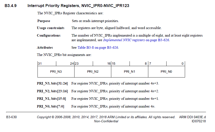
    NVIC interrupts are prioritized by updating an 8-bit field within a 32-bit register (each register supporting four interrupts). Priorities are maintained according to the ARMv7-M prioritization scheme.

    Maximum supported priority value

    The number of supported priority values is an IMPLEMENTATION DEFINED power of two in the range 8 to 256, and the minimum supported priority value is always 0. All priority value fields are 8-bits and if an implementation supports fewer than 256 priority levels then low-order bits of these fields are RAZ. 

    Table B1-6 Relation between number of priority bits and maximum priority value

    Number of priority bits          Number of priority levels       Maximum priority value a

    3                                              8                              0b11100000 = 224(0xE0)

    4                                              16                           0b11110000 = 240(0xF0)

    5                                              32                            0b11111000 = 248(0xF8)

    6                                              64                            0b11111100 = 252(0xFC)

    7                                              128                         0b11111110 = 254(0XFE)

    8                                              256                          0b11111111 = 255(0xFF)

    a. This value always corresponds to the lowest possible exception priority.

  • BTW: For table 3-9 to make any sense in (array below), then row one (0x0-0x4) infers encodings (7_1, 6_2, 5_3, 4_4, 3_5) can be used to set 5 priority groupings, not simply one (4_4). Otherwise table 3-9 column one (0x5, 0x6, 0x7) relate to array (2_6, 1_6, 0_8) respectively. Multiple Groupings in the binary split for NVIC preemption priority behavior is not being explained in datasheet text. It would seem the lower group has the highest priority grouping.

    Perhaps we should not simply lump all INT sources into priority group (4_4) as INT preemptions might go unhandled? Instead distribute INT pend hierarchy from most important peripheral to least within multiple (5 total priority groups) groupings, not 8 as shown in table 3-9. Doing such might benefit from high speed Tail Chaining between peripheral interrupt handlers. 

    This is a mapping between priority grouping encodings and the number of preemption priority bits.

    static const uint32_t g_pui32Priority[] =

    {

       NVIC_APINT_PRIGROUP_0_8, NVIC_APINT_PRIGROUP_1_7, NVIC_APINT_PRIGROUP_2_6,

       NVIC_APINT_PRIGROUP_3_5, NVIC_APINT_PRIGROUP_4_4, NVIC_APINT_PRIGROUP_5_3,

       NVIC_APINT_PRIGROUP_6_2, NVIC_APINT_PRIGROUP_7_1

    };

  • ARM Cortex M4 v7 reference PDF states NVIC supports 240 interrupts 256 levels of priority. It seems IntPrioritySet() configures some, not all priority group mappings shown ARM Cortex reference PDF table 6-1 . Point being 256 levels of priority are restricted to only 8 groups (REG58) does not even exist in ARM Cortex M4 v7 MCU? ARM reference manual does not indicate NVIC being restricted to 8 priority groups (0x00-0xE0) or 3 bit splits [7:5].

    ARM M4 v7 Interrupt Priority Register : 0xE000E400- 0xE000E4EC (NVIC_IPR0 - NVIC_IPR59) RW 0x00000000.

    Incomplete Tivaware priority range: [NVIC_PRI0 (0xE400) - NVIC_PRI34 (0xE488)].

    REG58:
    The PRIGROUP field indicates the position of the binary point that splits the INTx fields in the
    Interrupt Priority (PRIx) registers into separate group priority and subpriority fields. Table
    3-9 on page 171 shows how the PRIGROUP value controls this split. The bit numbers in the Group
    Priority Field and Subpriority Field columns in the table refer to the bits in the INTA field. For the
    INTB field, the corresponding bits are 15:13; for INTC, 23:21; and for INTD, 31:29.

    Where are INTA, INTB, INTC, INTD fields shown in Figure 3-9, bits 31:16 are for entry of intvect key value (0x0F5A)?
  • Modified post above as ARM system guide to NVIC indicates the binary split REG58 being the highest hex value in any single grouping.

    Also note ( INTA, INTB, INTC, INTD) above post are not shown in datasheet (REG58) seem to infer the NVIC table below should be referenced assigning any interrupts to specific groupings.

    It would seem priority grouping binary split (REG58) is incomplete when calling IntPriotryGroupingSet(). Seemingly relates to high NVIC latency (>400µs) when SS2 trigged via GPIO from priority group (0x40) samples signals resulting group (0x20), the lower priority groups interrupt handler must be delayed so application targets latency window as NVIC incorrectly preempts active pends in the lower priority group. There is no way on earth TM4C1294 NVIC should be preforming so oddly for several peripherals pending active edge or pulsed interrupts from Tivaware prioritized interrupts groupings.  

  • BP101 said:
    What happens next when PWM0 higher priority group is invoked, the lower priority group (TM0B/TM3A) can no longer preempt the higher group until the higher 80us PWM stops pending. That is not how NVIC priority chaining is supposed to work, read for yourself.

    I really don't get this statement at all, can you provide the document and page #'s that imply a lower priority group should have the ability to preempt a higher priority group? Or perhaps you misworded this?

    Rather than spend time trying to justify your system behavior with research into NVIC priorities, why don't you spend some time testing how much time your code takes from PWM ISR entry until ISR exit (which will only happen when all called functions within the ISR are resolved). Because until that PWM ISR is exited, no lower priority interrupts will be serviced. This problem is likely far more simple than you are trying to make it seem.

  • Hi Ralph,

    Ralph Jacobi said:
    ). Because until that PWM ISR is exited, no lower priority interrupts will be serviced. This problem is likely far more simple than you are trying to make it seem.

    The PWM generation code is entirely interrupt priority driven it is only in part a called function just to get started. Then NVIC takes over by prioritizing all other interrupt sources. The entire application is NVIC priority interrupt driven. The binary split Tivaware makes REG58 is not as ARM Cortex M4v7 manual shows. Proof disabling TM3A/TM0B interrupts indicates NVIC is not interleaving or prioritizing other lower priority interrupt sources relative to higher ones. The slower TM3A configured (1.1ms - 16.8ms) edge interrupts should be seamless periods relative to 80us PWM GEN0 pulsed interrupts.  

    Ralph Jacobi said:
    I really don't get this statement at all, can you provide the document and page #'s that imply a lower priority group should have the ability to preempt a higher priority group? Or perhaps you misworded this?

    The NVIC supports the following features:

    • NVIC interrupts can be enabled and disabled by writing to their corresponding Interrupt Set-Enable or Interrupt Clear-Enable register bit field. The registers use a write-1-to-enable and write-1-to-clear policy, both registers reading back the current enabled state of the corresponding (32) interrupts. When an interrupt is disabled, interrupt assertion causes the interrupt to become pending, but the interrupt cannot become active. If an interrupt is active when it is disabled, it remains in the active state until this is cleared by a reset or an exception return. Clearing the enable bit prevents any new activation of the associated interrupt.

    Disabling both GPTM interrupts and re-enabling them during the INT handlers proves NVIC priority handling does not remain consistent when PWM0 GEN0 interrupt vector occurs. The slower timers 30Hz-890Hz should remain seamless intervals within a few microseconds, not 100's of milliseconds or not at all when disabled. It seems the timer interrupts remain active but NEVER again preempt PWM0 GEN0 higher priority level in that test scenario. Behavior of interrupt handling makes it seem as if the Binary split 0x300, 0x400 and any others in REG58 are not truly being acknowledged by NVIC.

    Again the slower timer interval interrupts should remain seamless in the much faster pulsed interrupt sources of PWM0 GEN0 but do not. There is no way NVIC is not capable to control seamless priory interrupt cycles in this described scenario, so something ain't right! After all MCU clocks 150 DMIPS and 120Mhz M4 Cortex clock rates surround NVIC in this measly interrupt driven application. The ADC sample latency CADC (>400us) is yet another example how preemption of active priority pulsed interrupts is not as it should be. The only thing that explains PWM0 triggered ADC0 interrupts not keeping synchronous, again smells of priority grouping NVIC issues.  

  • Hello BP101,

    I think I understand where you have a misunderstanding. You said:

    BP101 said:
    The PWM generation code is entirely interrupt priority driven it is only in part a called function just to get started.

    What you may not realize is if you call that function, you are going to remain in the ISR until that function resolves. So you are not out of your PWM interrupt until the function finishes, and then when you finally exit the ISR, you can service the timers.

    Please run the test I instructed from the very beginning. Until you do that test and provide the results, I am not going to spend more time trying to explain this topic to you as to me it is very clear what is happening, so you need to observe this yourself to understand this, I can't explain it any better than I already have.

  • Hi Ralph,

    Ralph Jacobi said:
    What you may not realize is if you call that function, you are going to remain in the ISR until that function resolves. So you are not out of your PWM interrupt until the function finishes, and then when you finally exit the ISR, you can service the timers

    Past have confirmed 80us NVIC intervals exit via GPIO port probes; A 1ms tick SW interrupt also triggers inside the 80us PWM0 interrupt handler. The GPIO pin would remain high if PWM0 did not exit and not produce 1ms intervals on scope probe.

    Perhaps you misunderstand PWM0 interrupt handler DOES exit every 80us, (cleared twice) on entry. So the zero count interrupt does not stay in a perpetual pending/active state in the sense of NVIC handling. I was wrong to say TM3A timeout is only effected when PWM0 is active. PWM0 interrupt is always active (idle/run) states, only gates PWMENABLE (run state) loads GPTM4A Oneshot (400us) triggering ADC0 SS2 sample conversions and immediately exists that very fast call.

    So SS2(INT32) then pends INT priority above slower edge count (TM0B), Oneshot (TM3A) timers, all exist in the same priority grouping (0x40) of TM3A(INT51) and TM0B(INT36). Subpriority level 1 for (3:5, 4:4) splits are supposed to next determine pending/active order via the interrupt vector number. That SUB priority ordering is not working when SS2 or TM4A is active inside PMW0 run state activity of PWMENABLE (REG3). I didn't mention SS2 since it holds highest SUB priority level inside 0x40 grouping order.

    Datasheet states priority order within a priority grouping flows down to the sub priority interrupt level. Again the subpriority interrupt handling within priority groups is not working as it has been explained in the datasheet. Have I misunderstood that SUB priority NVIC handling of pend/active states relies next on the interrupt vector number with the same priority grouping?

  • This issues seems related to internal bus noise entering CCP circuit, most noticeable when PWMENABLE pins are driving voltage >24vdc. Grounding CCP input still produces edge counts but a faster interval, mostly as PWMENABLE register goes active. As of this post had not confirmed the edge count value remains the same during PWMENABLE, as it did during idle time.

    Seemingly reverse current may be flowing from 3 gate drivers into the GPIO pins of PWM0 or digital ground. Those pins are pulled down digital ground via 20K near MCU pins. The six pins slew rate, drive strength are PAD configured for GPIO_STRENGTH_8MA_SC.
  • Hi Ralph,

    A bit more information has been collected to identify why edge counts seem to stray in interrupt vector contexts. This issue has more to do with high frequency invading low frequency CCP as disused in above post. That seems to affect the edge count/time interrupt handlers in a bad way.
  • Hello BP101,

    There would not be internal noise causing such issues between those modules, if you believe that you have identified noise issues then that is noise being injected into the device from outside. You should do some testing on any pins affected and all ground pins to see if you can track down the source of the noise injection to then minimize it.
  • Hi Ralph,

    Yet noise from outside pins does not explain when grounding PL5 CCP1 input still toggles notably when GPTM1A Oneshot interrupts of PWMENABLE cycles. Mux decodes used in GPIOPinConfigure() attained from (pin_mux.h) used to select AHB versus APB aperture for ports via (gpio.c) and register (GPIO_O_CTRL) supposedly not existing in TM4C1294 is alarming. Note GPTM1A has two CCP pins and are not being assigned to a GPIO port control far as the application is concerned. However if configuration SW is doing something obscure behind the observation of CCS debug, no body would be aware until mayhem occurs. 

    Amit post reply (links below) seems to confirm GPIO_O_CTRL still exists but was removed from the datasheet.

    https://e2e.ti.com/support/microcontrollers/other/f/908/p/374119/1316366 

    https://e2e.ti.com/support/microcontrollers/other/f/908/p/374119/1316370#1316370

    The lower GPIO ports A-H remain for low port APB aperture decodes (gpio.c) and APB still exists (Figure 1-1) architecture block diagram. So GPTM0B CCP1 port (AHB_PL5) used in edge counts may overlap with GPTM1A Oneshot CCP0 (not configured). The change in speed of edge counts frequency GPTM0B is not noticeable at slower GPTM1A re-load events. Again PL5 is grounded so the edge counts on CCP1 are occurring inside the GPIO digital Mux. There seems to be an internal link between CCP in Five TM4C1294KCPDT tested in this issue of possible cross linked decodes.

    Seemingly a cross linked decode in GPIO port control register occurs and is not as noticeable at low frequency GPTM tick rates. Running the math GPIOPinConfigure() aperture algorithm via a calculator one time revealed the case may exist for some AHB upper ports (J-S) pin_mux.h decodes to overlap. Also the lower part of port demux algorithm produces an Qword overflow in the NOT operation, that can't be good.


  • Hello BP101,

    If noise is not the source of the issue, then you should have no issue reproducing this behavior on a LaunchPad so you can provide a code project with your settings that we can test and debug on our end to investigate this claim. Can you please configure the GPIO & Timers on a LaunchPad to match your application and see if you can replicate the issue outside of your system? If so, then I can look into this further as it would then be proven to be a device behavior that needs to be further understood and has nothing to do with your system.

    As far the APB vs AHB post, what Amit was trying to say is that when used properly TivaWare will ensure that AHB routing is done and to not try and manually use APB as it is not spec'd and could cause bus faults. As long as you are using TivaWare registers, you'll be fine.
  • Since this discussion split into a new thread I am closing this one: e2e.ti.com/.../2927732