Hey Forum,
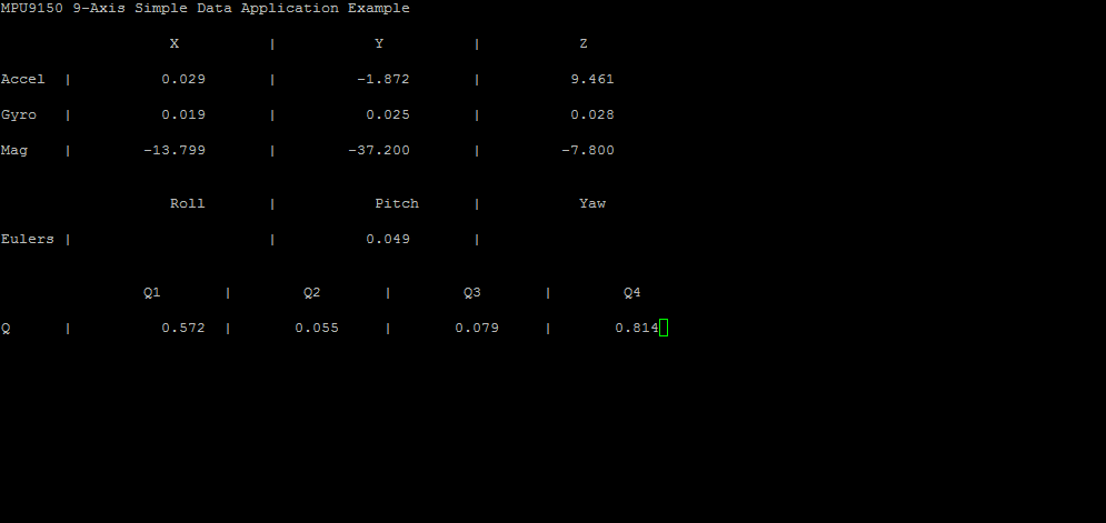
My issue is with using the UART output to the putty terminal. I was attempting to mimic the output of the demo sensorHub code displayed below....
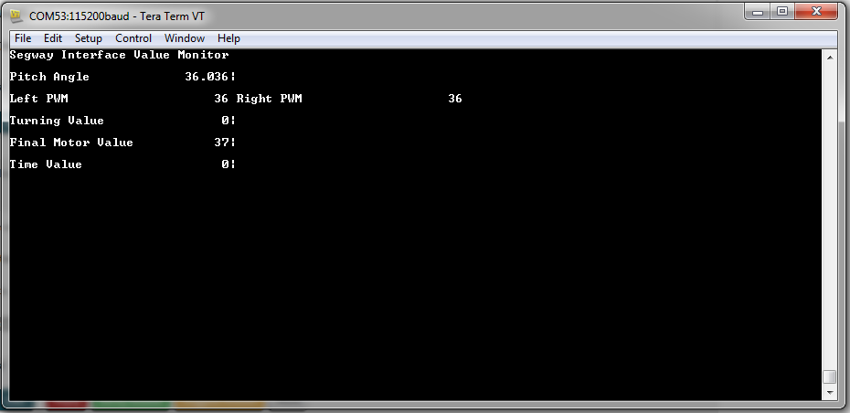
 I was trying to use the same format to display data from my own project (DIY Segway) but i was running into some issues. I have configured my UART the same but my output is not as near to the example. My output is shown below......
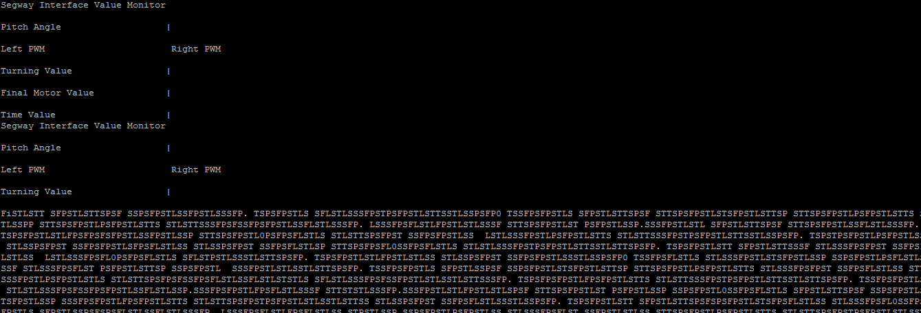 The value options repeat and then i believe my uart is overflowed with information. So what im am trying to achieve is a way to demonstrate my data without the UART constantly repeating the variable names and only updating the variable number.
I have my code attached below and i have posted the sensor hub demo code as well.
MY CODE:
void initUart()
{
	SysCtlPeripheralEnable(SYSCTL_PERIPH_GPIOA);
	SysCtlPeripheralEnable(SYSCTL_PERIPH_UART0);
	GPIOPinConfigure(GPIO_PA0_U0RX);
	GPIOPinConfigure(GPIO_PA1_U0TX);
	GPIOPinTypeUART(GPIO_PORTA_BASE, GPIO_PIN_0 | GPIO_PIN_1);
	UARTClockSourceSet(UART0_BASE, UART_CLOCK_PIOSC);
	UARTStdioConfig(0, 115200, 16000000);
}

void outputData(int LeftPWM, int RightPWM, int turningVal, int timeVal, int finalMotorVal,int pitchVal, int pitchDeci)
{

    UARTprintf("\033[2J\033[H");
    UARTprintf("Segway Interface Value Monitor\n\n");
    UARTprintf("Pitch Angle\033[31G|\n\n");//accel
    UARTprintf("Left PWM\033[31G Right PWM\n\n");//[54G|
    UARTprintf("Turning Value\033[31G|\n\n");
    UARTprintf("Final Motor Value\033[31G|\n\n");
    UARTprintf("Time Value\033[31G|\n\n");

	g_ui32PrintSkipCounter++;
	if(g_ui32PrintSkipCounter >= PRINT_SKIP_COUNT)
	{
		//
		// Reset skip counter.
		//
		g_ui32PrintSkipCounter = 0;

        UARTprintf("\033[5;17H%3d.%03d", pitchVal, pitchDeci);
        UARTprintf("\033[7;17H%3d %3d", LeftPWM, RightPWM);
        UARTprintf("\033[9;17H%3d", turningVal);
        UARTprintf("\033[19;14H%3d", finalMotorVal);
        UARTprintf("\033[19;17H%3d", timeVal);

	}

}
SENSORHUB CODE:
//*****************************************************************************
//
// compdcm_mpu9150.c - Example use of the SensorLib with the MPU9150
//
// Copyright (c) 2013-2015 Texas Instruments Incorporated.  All rights reserved.
// Software License Agreement
//
// Texas Instruments (TI) is supplying this software for use solely and
// exclusively on TI's microcontroller products. The software is owned by
// TI and/or its suppliers, and is protected under applicable copyright
// laws. You may not combine this software with "viral" open-source
// software in order to form a larger program.
//
// THIS SOFTWARE IS PROVIDED "AS IS" AND WITH ALL FAULTS.
// NO WARRANTIES, WHETHER EXPRESS, IMPLIED OR STATUTORY, INCLUDING, BUT
// NOT LIMITED TO, IMPLIED WARRANTIES OF MERCHANTABILITY AND FITNESS FOR
// A PARTICULAR PURPOSE APPLY TO THIS SOFTWARE. TI SHALL NOT, UNDER ANY
// CIRCUMSTANCES, BE LIABLE FOR SPECIAL, INCIDENTAL, OR CONSEQUENTIAL
// DAMAGES, FOR ANY REASON WHATSOEVER.
//
// This is part of revision 2.1.2.111 of the EK-TM4C123GXL Firmware Package.
//
//*****************************************************************************

#include <stdint.h>
#include <stdbool.h>
#include "inc/hw_memmap.h"
#include "inc/hw_ints.h"
#include "driverlib/debug.h"
#include "driverlib/gpio.h"
#include "driverlib/interrupt.h"
#include "driverlib/pin_map.h"
#include "driverlib/rom.h"
#include "driverlib/sysctl.h"
#include "driverlib/uart.h"
#include "utils/uartstdio.h"
#include "sensorlib/hw_mpu9150.h"
#include "sensorlib/hw_ak8975.h"
#include "sensorlib/i2cm_drv.h"
#include "sensorlib/ak8975.h"
#include "sensorlib/mpu9150.h"
#include "sensorlib/comp_dcm.h"
#include "drivers/rgb.h"

//*****************************************************************************
//
//! \addtogroup example_list
//! <h1>Nine Axis Sensor Fusion with the MPU9150 and Complimentary-Filtered
//! DCM (compdcm_mpu9150)</h1>
//!
//! This example demonstrates the basic use of the Sensor Library, TM4C123G
//! LaunchPad and SensHub BoosterPack to obtain nine axis motion measurements
//! from the MPU9150.  The example fuses the nine axis measurements into a set
//! of Euler angles: roll, pitch and yaw.  It also produces the rotation
//! quaternions.  The fusion mechanism demonstrated is complimentary-filtered
//! direct cosine matrix (DCM) algorithm is provided as part of the Sensor
//! Library.
//!
//! Connect a serial terminal program to the LaunchPad's ICDI virtual serial
//! port at 115,200 baud.  Use eight bits per byte, no parity and one stop bit.
//! The raw sensor measurements, Euler angles and quaternions are printed to
//! the terminal.  The RGB LED begins to blink at 1Hz after initialization is
//! completed and the example application is running.
//
//*****************************************************************************

//*****************************************************************************
//
// Define MPU9150 I2C Address.
//
//*****************************************************************************
#define MPU9150_I2C_ADDRESS     0x68

//*****************************************************************************
//
// Global array for holding the color values for the RGB.
//
//*****************************************************************************
uint32_t g_pui32Colors[3];

//*****************************************************************************
//
// Global instance structure for the I2C master driver.
//
//*****************************************************************************
tI2CMInstance g_sI2CInst;

//*****************************************************************************
//
// Global instance structure for the ISL29023 sensor driver.
//
//*****************************************************************************
tMPU9150 g_sMPU9150Inst;

//*****************************************************************************
//
// Global Instance structure to manage the DCM state.
//
//*****************************************************************************
tCompDCM g_sCompDCMInst;

//*****************************************************************************
//
// Global flags to alert main that MPU9150 I2C transaction is complete
//
//*****************************************************************************
volatile uint_fast8_t g_vui8I2CDoneFlag;

//*****************************************************************************
//
// Global flags to alert main that MPU9150 I2C transaction error has occurred.
//
//*****************************************************************************
volatile uint_fast8_t g_vui8ErrorFlag;

//*****************************************************************************
//
// Global flags to alert main that MPU9150 data is ready to be retrieved.
//
//*****************************************************************************
volatile uint_fast8_t g_vui8DataFlag;

//*****************************************************************************
//
// Global counter to control and slow down the rate of data to the terminal.
//
//*****************************************************************************
#define PRINT_SKIP_COUNT        10

uint32_t g_ui32PrintSkipCounter;

//*****************************************************************************
//
// The error routine that is called if the driver library encounters an error.
//
//*****************************************************************************
#ifdef DEBUG
void
__error__(char *pcFilename, uint32_t ui32Line)
{
}
#endif

//*****************************************************************************
//
// MPU9150 Sensor callback function.  Called at the end of MPU9150 sensor
// driver transactions. This is called from I2C interrupt context. Therefore,
// we just set a flag and let main do the bulk of the computations and display.
//
//*****************************************************************************
void
MPU9150AppCallback(void *pvCallbackData, uint_fast8_t ui8Status)
{
    //
    // If the transaction succeeded set the data flag to indicate to
    // application that this transaction is complete and data may be ready.
    //
    if(ui8Status == I2CM_STATUS_SUCCESS)
    {
        g_vui8I2CDoneFlag = 1;
    }

    //
    // Store the most recent status in case it was an error condition
    //
    g_vui8ErrorFlag = ui8Status;
}

//*****************************************************************************
//
// Called by the NVIC as a result of GPIO port B interrupt event. For this
// application GPIO port B pin 2 is the interrupt line for the MPU9150
//
//*****************************************************************************
void
IntGPIOb(void)
{
    unsigned long ulStatus;

    ulStatus = GPIOIntStatus(GPIO_PORTB_BASE, true);

    //
    // Clear all the pin interrupts that are set
    //
    GPIOIntClear(GPIO_PORTB_BASE, ulStatus);

    if(ulStatus & GPIO_PIN_2)
    {
        //
        // MPU9150 Data is ready for retrieval and processing.
        //
        MPU9150DataRead(&g_sMPU9150Inst, MPU9150AppCallback, &g_sMPU9150Inst);
    }
}

//*****************************************************************************
//
// Called by the NVIC as a result of I2C3 Interrupt. I2C3 is the I2C connection
// to the MPU9150.
//
//*****************************************************************************
void
MPU9150I2CIntHandler(void)
{
    //
    // Pass through to the I2CM interrupt handler provided by sensor library.
    // This is required to be at application level so that I2CMIntHandler can
    // receive the instance structure pointer as an argument.
    //
    I2CMIntHandler(&g_sI2CInst);
}

//*****************************************************************************
//
// MPU9150 Application error handler. Show the user if we have encountered an
// I2C error.
//
//*****************************************************************************
void
MPU9150AppErrorHandler(char *pcFilename, uint_fast32_t ui32Line)
{
    //
    // Set terminal color to red and print error status and locations
    //
    UARTprintf("\033[31;1m");
    UARTprintf("Error: %d, File: %s, Line: %d\n"
               "See I2C status definitions in sensorlib\\i2cm_drv.h\n",
               g_vui8ErrorFlag, pcFilename, ui32Line);

    //
    // Return terminal color to normal
    //
    UARTprintf("\033[0m");

    //
    // Set RGB Color to RED
    //
    g_pui32Colors[0] = 0xFFFF;
    g_pui32Colors[1] = 0;
    g_pui32Colors[2] = 0;
    RGBColorSet(g_pui32Colors);

    //
    // Increase blink rate to get attention
    //
    RGBBlinkRateSet(10.0f);

    //
    // Go to sleep wait for interventions.  A more robust application could
    // attempt corrective actions here.
    //
    while(1)
    {
        //
        // Do Nothing
        //
    }
}

//*****************************************************************************
//
// Function to wait for the MPU9150 transactions to complete. Use this to spin
// wait on the I2C bus.
//
//*****************************************************************************
void
MPU9150AppI2CWait(char *pcFilename, uint_fast32_t ui32Line)
{
    //
    // Put the processor to sleep while we wait for the I2C driver to
    // indicate that the transaction is complete.
    //
    while((g_vui8I2CDoneFlag == 0) && (g_vui8ErrorFlag == 0))
    {
        //
        // Do Nothing
        //
    }

    //
    // If an error occurred call the error handler immediately.
    //
    if(g_vui8ErrorFlag)
    {
        MPU9150AppErrorHandler(pcFilename, ui32Line);
    }

    //
    // clear the data flag for next use.
    //
    g_vui8I2CDoneFlag = 0;
}

//*****************************************************************************
//
// Configure the UART and its pins.  This must be called before UARTprintf().
//
//*****************************************************************************
void
ConfigureUART(void)
{
    //
    // Enable the GPIO Peripheral used by the UART.
    //
    ROM_SysCtlPeripheralEnable(SYSCTL_PERIPH_GPIOA);

    //
    // Enable UART0
    //
    ROM_SysCtlPeripheralEnable(SYSCTL_PERIPH_UART0);

    //
    // Configure GPIO Pins for UART mode.
    //
    ROM_GPIOPinConfigure(GPIO_PA0_U0RX);
    ROM_GPIOPinConfigure(GPIO_PA1_U0TX);
    ROM_GPIOPinTypeUART(GPIO_PORTA_BASE, GPIO_PIN_0 | GPIO_PIN_1);

    //
    // Use the internal 16MHz oscillator as the UART clock source.
    //
    UARTClockSourceSet(UART0_BASE, UART_CLOCK_PIOSC);

    //
    // Initialize the UART for console I/O.
    //
    UARTStdioConfig(0, 115200, 16000000);
}

//*****************************************************************************
//
// Main application entry point.
//
//*****************************************************************************
int
main(void)
{
    int_fast32_t i32IPart[16], i32FPart[16];
    uint_fast32_t ui32Idx, ui32CompDCMStarted;
    float pfData[16];
    float *pfAccel, *pfGyro, *pfMag, *pfEulers, *pfQuaternion;

    //
    // Initialize convenience pointers that clean up and clarify the code
    // meaning. We want all the data in a single contiguous array so that
    // we can make our pretty printing easier later.
    //
    pfAccel = pfData;
    pfGyro = pfData + 3;
    pfMag = pfData + 6;
    pfEulers = pfData + 9;
    pfQuaternion = pfData + 12;

    //
    // Setup the system clock to run at 40 Mhz from PLL with crystal reference
    //
    ROM_SysCtlClockSet(SYSCTL_SYSDIV_5 | SYSCTL_USE_PLL | SYSCTL_XTAL_16MHZ |
                       SYSCTL_OSC_MAIN);

    //
    // Enable port B used for motion interrupt.
    //
    ROM_SysCtlPeripheralEnable(SYSCTL_PERIPH_GPIOB);

    //
    // Initialize the UART.
    //
    ConfigureUART();

    //
    // Print the welcome message to the terminal.
    //
    UARTprintf("\033[2JMPU9150 Raw Example\n");

    //
    // Set the color to a purple approximation.
    //
    g_pui32Colors[RED] = 0x8000;
    g_pui32Colors[BLUE] = 0x8000;
    g_pui32Colors[GREEN] = 0x0000;

    //
    // Initialize RGB driver.
    //
    RGBInit(0);
    RGBColorSet(g_pui32Colors);
    RGBIntensitySet(0.5f);
    RGBEnable();

    //
    // The I2C3 peripheral must be enabled before use.
    //
    ROM_SysCtlPeripheralEnable(SYSCTL_PERIPH_I2C3);
    ROM_SysCtlPeripheralEnable(SYSCTL_PERIPH_GPIOD);

    //
    // Configure the pin muxing for I2C3 functions on port D0 and D1.
    //
    ROM_GPIOPinConfigure(GPIO_PD0_I2C3SCL);
    ROM_GPIOPinConfigure(GPIO_PD1_I2C3SDA);

    //
    // Select the I2C function for these pins.  This function will also
    // configure the GPIO pins pins for I2C operation, setting them to
    // open-drain operation with weak pull-ups.  Consult the data sheet
    // to see which functions are allocated per pin.
    //
    GPIOPinTypeI2CSCL(GPIO_PORTD_BASE, GPIO_PIN_0);
    ROM_GPIOPinTypeI2C(GPIO_PORTD_BASE, GPIO_PIN_1);

    //
    // Configure and Enable the GPIO interrupt. Used for INT signal from the
    // MPU9150
    //
    ROM_GPIOPinTypeGPIOInput(GPIO_PORTB_BASE, GPIO_PIN_2);
    GPIOIntEnable(GPIO_PORTB_BASE, GPIO_PIN_2);
    ROM_GPIOIntTypeSet(GPIO_PORTB_BASE, GPIO_PIN_2, GPIO_FALLING_EDGE);
    ROM_IntEnable(INT_GPIOB);

    //
    // Keep only some parts of the systems running while in sleep mode.
    // GPIOB is for the MPU9150 interrupt pin.
    // UART0 is the virtual serial port
    // TIMER0, TIMER1 and WTIMER5 are used by the RGB driver
    // I2C3 is the I2C interface to the ISL29023
    //
    ROM_SysCtlPeripheralClockGating(true);
    ROM_SysCtlPeripheralSleepEnable(SYSCTL_PERIPH_GPIOB);
    ROM_SysCtlPeripheralSleepEnable(SYSCTL_PERIPH_UART0);
    ROM_SysCtlPeripheralSleepEnable(SYSCTL_PERIPH_TIMER0);
    ROM_SysCtlPeripheralSleepEnable(SYSCTL_PERIPH_TIMER1);
    ROM_SysCtlPeripheralSleepEnable(SYSCTL_PERIPH_I2C3);
    ROM_SysCtlPeripheralSleepEnable(SYSCTL_PERIPH_WTIMER5);

    //
    // Enable interrupts to the processor.
    //
    ROM_IntMasterEnable();

    //
    // Initialize I2C3 peripheral.
    //
    I2CMInit(&g_sI2CInst, I2C3_BASE, INT_I2C3, 0xff, 0xff,
             ROM_SysCtlClockGet());

    //
    // Initialize the MPU9150 Driver.
    //
    MPU9150Init(&g_sMPU9150Inst, &g_sI2CInst, MPU9150_I2C_ADDRESS,
                MPU9150AppCallback, &g_sMPU9150Inst);

    //
    // Wait for transaction to complete
    //
    MPU9150AppI2CWait(__FILE__, __LINE__);

    //
    // Write application specifice sensor configuration such as filter settings
    // and sensor range settings.
    //
    g_sMPU9150Inst.pui8Data[0] = MPU9150_CONFIG_DLPF_CFG_94_98;
    g_sMPU9150Inst.pui8Data[1] = MPU9150_GYRO_CONFIG_FS_SEL_250;
    g_sMPU9150Inst.pui8Data[2] = (MPU9150_ACCEL_CONFIG_ACCEL_HPF_5HZ |
                                  MPU9150_ACCEL_CONFIG_AFS_SEL_2G);
    MPU9150Write(&g_sMPU9150Inst, MPU9150_O_CONFIG, g_sMPU9150Inst.pui8Data, 3,
                 MPU9150AppCallback, &g_sMPU9150Inst);

    //
    // Wait for transaction to complete
    //
    MPU9150AppI2CWait(__FILE__, __LINE__);

    //
    // Configure the data ready interrupt pin output of the MPU9150.
    //
    g_sMPU9150Inst.pui8Data[0] = MPU9150_INT_PIN_CFG_INT_LEVEL |
                                    MPU9150_INT_PIN_CFG_INT_RD_CLEAR |
                                    MPU9150_INT_PIN_CFG_LATCH_INT_EN;
    g_sMPU9150Inst.pui8Data[1] = MPU9150_INT_ENABLE_DATA_RDY_EN;
    MPU9150Write(&g_sMPU9150Inst, MPU9150_O_INT_PIN_CFG,
                 g_sMPU9150Inst.pui8Data, 2, MPU9150AppCallback,
                 &g_sMPU9150Inst);

    //
    // Wait for transaction to complete
    //
    MPU9150AppI2CWait(__FILE__, __LINE__);

    //
    // Initialize the DCM system. 50 hz sample rate.
    // accel weight = .2, gyro weight = .8, mag weight = .2
    //
    CompDCMInit(&g_sCompDCMInst, 1.0f / 50.0f, 0.2f, 0.6f, 0.2f);

    UARTprintf("\033[2J\033[H");
    UARTprintf("MPU9150 9-Axis Simple Data Application Example\n\n");
    UARTprintf("\033[20GX\033[31G|\033[43GY\033[54G|\033[66GZ\n\n");
    UARTprintf("Accel\033[8G|\033[31G|\033[54G|\n\n");
    UARTprintf("Gyro\033[8G|\033[31G|\033[54G|\n\n");
    UARTprintf("Mag\033[8G|\033[31G|\033[54G|\n\n");
    UARTprintf("\n\033[20GRoll\033[31G|\033[43GPitch\033[54G|\033[66GYaw\n\n");
    UARTprintf("Eulers\033[8G|\033[31G|\033[54G|\n\n");

    UARTprintf("\n\033[17GQ1\033[26G|\033[35GQ2\033[44G|\033[53GQ3\033[62G|"
               "\033[71GQ4\n\n");
    UARTprintf("Q\033[8G|\033[26G|\033[44G|\033[62G|\n\n");

    //
    // Enable blinking indicates config finished successfully
    //
    RGBBlinkRateSet(1.0f);

    ui32CompDCMStarted = 0;

    while(1)
    {
        //
        // Go to sleep mode while waiting for data ready.
        //
        while(!g_vui8I2CDoneFlag)
        {
            ROM_SysCtlSleep();
        }

        //
        // Clear the flag
        //
        g_vui8I2CDoneFlag = 0;

        //
        // Get floating point version of the Accel Data in m/s^2.
        //
        MPU9150DataAccelGetFloat(&g_sMPU9150Inst, pfAccel, pfAccel + 1,
                                 pfAccel + 2);

        //
        // Get floating point version of angular velocities in rad/sec
        //
        MPU9150DataGyroGetFloat(&g_sMPU9150Inst, pfGyro, pfGyro + 1,
                                pfGyro + 2);

        //
        // Get floating point version of magnetic fields strength in tesla
        //
        MPU9150DataMagnetoGetFloat(&g_sMPU9150Inst, pfMag, pfMag + 1,
                                   pfMag + 2);

        //
        // Check if this is our first data ever.
        //
        if(ui32CompDCMStarted == 0)
        {
            //
            // Set flag indicating that DCM is started.
            // Perform the seeding of the DCM with the first data set.
            //
            ui32CompDCMStarted = 1;
            CompDCMMagnetoUpdate(&g_sCompDCMInst, pfMag[0], pfMag[1],
                                 pfMag[2]);
            CompDCMAccelUpdate(&g_sCompDCMInst, pfAccel[0], pfAccel[1],
                               pfAccel[2]);
            CompDCMGyroUpdate(&g_sCompDCMInst, pfGyro[0], pfGyro[1],
                              pfGyro[2]);
            CompDCMStart(&g_sCompDCMInst);
        }
        else
        {
            //
            // DCM Is already started.  Perform the incremental update.
            //
            CompDCMMagnetoUpdate(&g_sCompDCMInst, pfMag[0], pfMag[1],
                                 pfMag[2]);
            CompDCMAccelUpdate(&g_sCompDCMInst, pfAccel[0], pfAccel[1],
                               pfAccel[2]);
            CompDCMGyroUpdate(&g_sCompDCMInst, -pfGyro[0], -pfGyro[1],
                              -pfGyro[2]);
            CompDCMUpdate(&g_sCompDCMInst);
        }

        //
        // Increment the skip counter.  Skip counter is used so we do not
        // overflow the UART with data.
        //
        g_ui32PrintSkipCounter++;
        if(g_ui32PrintSkipCounter >= PRINT_SKIP_COUNT)
        {
            //
            // Reset skip counter.
            //
            g_ui32PrintSkipCounter = 0;

            //
            // Get Euler data. (Roll Pitch Yaw)
            //
            CompDCMComputeEulers(&g_sCompDCMInst, pfEulers, pfEulers + 1,
                                 pfEulers + 2);

            //
            // Get Quaternions.
            //
            CompDCMComputeQuaternion(&g_sCompDCMInst, pfQuaternion);

            //
            // convert mag data to micro-tesla for better human interpretation.
            //
            pfMag[0] *= 1e6;
            pfMag[1] *= 1e6;
            pfMag[2] *= 1e6;

            //
            // Convert Eulers to degrees. 180/PI = 57.29...
            // Convert Yaw to 0 to 360 to approximate compass headings.
            //
            pfEulers[0] *= 57.295779513082320876798154814105f;
            pfEulers[1] *= 57.295779513082320876798154814105f;
            pfEulers[2] *= 57.295779513082320876798154814105f;
            if(pfEulers[2] < 0)
            {
                pfEulers[2] += 360.0f;
            }

            //
            // Now drop back to using the data as a single array for the
            // purpose of decomposing the float into a integer part and a
            // fraction (decimal) part.
            //
            for(ui32Idx = 0; ui32Idx < 16; ui32Idx++)
            {
                //
                // Conver float value to a integer truncating the decimal part.
                //
                i32IPart[ui32Idx] = (int32_t) pfData[ui32Idx];

                //
                // Multiply by 1000 to preserve first three decimal values.
                // Truncates at the 3rd decimal place.
                //
                i32FPart[ui32Idx] = (int32_t) (pfData[ui32Idx] * 1000.0f);

                //
                // Subtract off the integer part from this newly formed decimal
                // part.
                //
                i32FPart[ui32Idx] = i32FPart[ui32Idx] -
                                    (i32IPart[ui32Idx] * 1000);

                //
                // make the decimal part a positive number for display.
                //
                if(i32FPart[ui32Idx] < 0)
                {
                    i32FPart[ui32Idx] *= -1;
                }
            }

            //
            // Print the acceleration numbers in the table.
            //
            UARTprintf("\033[5;17H%3d.%03d", i32IPart[0], i32FPart[0]);
            UARTprintf("\033[5;40H%3d.%03d", i32IPart[1], i32FPart[1]);
            UARTprintf("\033[5;63H%3d.%03d", i32IPart[2], i32FPart[2]);

            //
            // Print the angular velocities in the table.
            //
            UARTprintf("\033[7;17H%3d.%03d", i32IPart[3], i32FPart[3]);
            UARTprintf("\033[7;40H%3d.%03d", i32IPart[4], i32FPart[4]);
            UARTprintf("\033[7;63H%3d.%03d", i32IPart[5], i32FPart[5]);

            //
            // Print the magnetic data in the table.
            //
            UARTprintf("\033[9;17H%3d.%03d", i32IPart[6], i32FPart[6]);
            UARTprintf("\033[9;40H%3d.%03d", i32IPart[7], i32FPart[7]);
            UARTprintf("\033[9;63H%3d.%03d", i32IPart[8], i32FPart[8]);

            //
            // Print the Eulers in a table.
            //
           // UARTprintf("\033[14;17H%3d.%03d", i32IPart[9], i32FPart[9]);
            UARTprintf("\033[14;40H%3d.%03d", i32IPart[10], i32FPart[10]);
           // UARTprintf("\033[14;63H%3d.%03d", i32IPart[11], i32FPart[11]);

            //
            // Print the quaternions in a table format.
            //
            UARTprintf("\033[19;17H%3d.%03d", i32IPart[12], i32FPart[12]);
            UARTprintf("\033[19;32H%3d.%03d", i32IPart[13], i32FPart[13]);
            UARTprintf("\033[19;50H%3d.%03d", i32IPart[14], i32FPart[14]);
            UARTprintf("\033[19;68H%3d.%03d", i32IPart[15], i32FPart[15]);

        }
    }
}
I hope my post is clear enough to understand! Please Help!