


Other Parts Discussed in Thread: EK-TM4C123GXL
I am starting to learn how to use timers/interrupts on the TM4C123 evaluation board (TM4C123GH6PM MCU).
In this example I am configuring a timer to create 1 second delays to toggle an on-board LED on and off. But when I run the code in real time on the board, the red LED appears to be on all the time. If I step through the code with breakpoints in my `while(1)` loop where I poll the timer register, it appears to work fine. (I am not using interrupts with this timer, just polling).
I haven't attached the individual register breakdowns from the datasheet as there are quite a few.
Has anyone got any ideas as to why this is not working as expected?
Below is my code for the example I am following from the TM4C123 datasheet:
And here is my code:
#include "include/tm4c123gh6pm.h"
#define RED_LED (1U << 1)
#define BLUE_LED (1U << 2)
#define GREEN_LED (1U << 3)
int main()
{
SYSCTL_RCGCGPIO_R = 0x20U; //Enabling clock to port F.
GPIO_PORTF_LOCK_R = 0x4C4F434BU; //Unlocking the port F lock register.
GPIO_PORTF_CR_R = 0xFFU; //Enabling the port F commit register.
GPIO_PORTF_DIR_R = 0x0EU; //Setting the port F pins as outputs.
GPIO_PORTF_DEN_R = 0x1FU; //Enabling digital writing to port F.
/* To use a GPTM, the appropriate TIMERn bit must be set in the RCGCTIMER or RCGCWTIMER
register (see page 338 and page 357). If using any CCP pins, the clock to the appropriate GPIO
module must be enabled via the RCGCGPIO register (see page 340). To find out which GPIO port
to enable, refer to Table 23-4 on page 1344. Configure the PMCn fields in the GPIOPCTL register to
assign the CCP signals to the appropriate pins (see page 688 and Table 23-5 on page 1351). */
SYSCTL_RCGCTIMER_R = 0x01U; //Enable timer 0 clock signal.
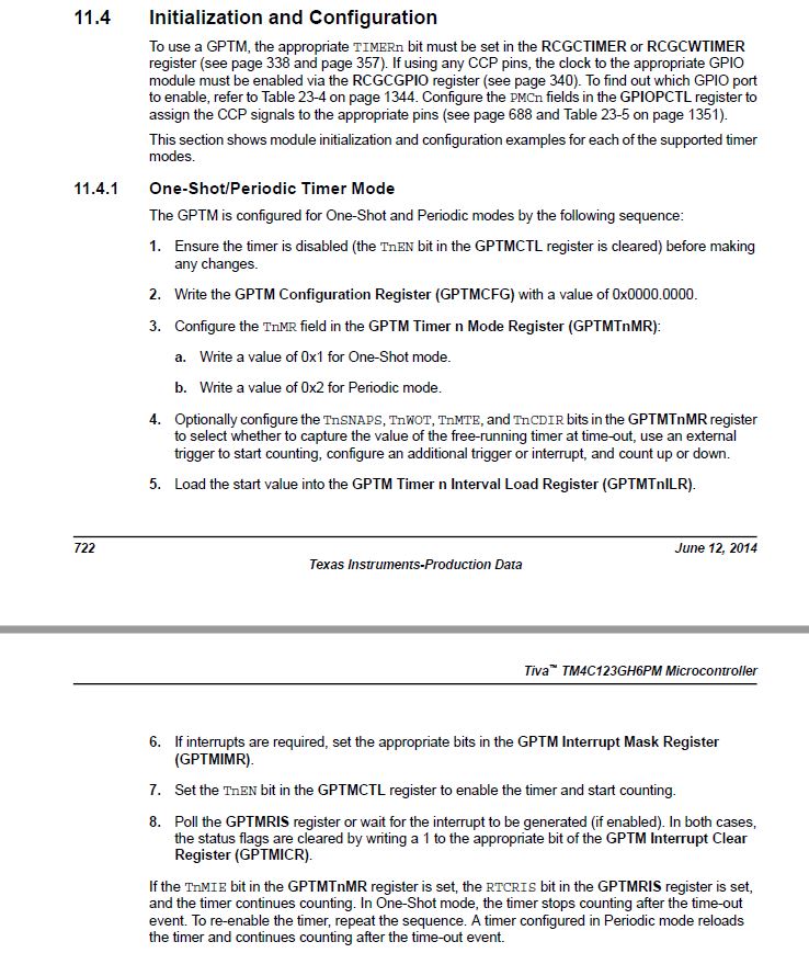
/* 1. Ensure the timer is disabled (the TnEN bit in the GPTMCTL register is cleared) before making
any changes. */
TIMER0_CTL_R &= ~(1<<0); //Disabling timer.
/* 2. Write the GPTM Configuration Register (GPTMCFG) with a value of 0x0000.0000. */
TIMER0_CFG_R = 0x00000000U; //Writing 0 hex to this register.
/* 3. Configure the TnMR field in the GPTM Timer n Mode Register (GPTMTnMR):
a. Write a value of 0x1 for One-Shot mode.
b. Write a value of 0x2 for Periodic mode. */
TIMER0_TAMR_R |= (0x2<<0); //Setting timer 0 to periodic mode.
/* 4. Optionally configure the TnSNAPS, TnWOT, TnMTE, and TnCDIR bits in the GPTMTnMR register
to select whether to capture the value of the free-running timer at time-out, use an external
trigger to start counting, configure an additional trigger or interrupt, and count up or down. */
TIMER0_TAMR_R &= ~(1<<4); //Configured as count down timer.
/* 5. Load the start value into the GPTM Timer n Interval Load Register (GPTMTnILR). */
TIMER0_TAILR_R = 0x00F42400; //16,000,000Mhz clock, 1 sec delays.
/* 6. If interrupts are required, set the appropriate bits in the GPTM Interrupt Mask Register
(GPTMIMR). */
//Interrupts are not used, I am polling the timer0 regsiter as seen below in while(1) loop.
/* 7. Set the TnEN bit in the GPTMCTL register to enable the timer and start counting. */
TIMER0_CTL_R |= (1<<0); //Enabling timer
/* 8. Poll the GPTMRIS register or wait for the interrupt to be generated (if enabled). In both cases,
the status flags are cleared by writing a 1 to the appropriate bit of the GPTM Interrupt Clear
Register (GPTMICR). */
while(1)
{
if( (TIMER0_RIS_R & 0x00000001) == 1) //Checking if timer has finished counting.
TIMER0_ICR_R |= (1<<0); //Clearing the finished timing bit in TIMER0_RIS_R.
GPIO_PORTF_DATA_R ^= (1U << 1); //Toggling the RED_LED output.
}
}
#define RED_LED (1U << 1)
#define BLUE_LED (1U << 2)
#define GREEN_LED (1U << 3)
int main()
{
SYSCTL_RCGCGPIO_R = 0x20U; //Enabling clock to port F.
GPIO_PORTF_LOCK_R = 0x4C4F434BU; //Unlocking the port F lock register.
GPIO_PORTF_CR_R = 0xFFU; //Enabling the port F commit register.
GPIO_PORTF_DIR_R = 0x0EU; //Setting the port F pins as outputs.
GPIO_PORTF_DEN_R = 0x1FU; //Enabling digital writing to port F.
/* To use a GPTM, the appropriate TIMERn bit must be set in the RCGCTIMER or RCGCWTIMER
register (see page 338 and page 357). If using any CCP pins, the clock to the appropriate GPIO
module must be enabled via the RCGCGPIO register (see page 340). To find out which GPIO port
to enable, refer to Table 23-4 on page 1344. Configure the PMCn fields in the GPIOPCTL register to
assign the CCP signals to the appropriate pins (see page 688 and Table 23-5 on page 1351). */
SYSCTL_RCGCTIMER_R = 0x01U; //Enable timer 0 clock signal.
/* 1. Ensure the timer is disabled (the TnEN bit in the GPTMCTL register is cleared) before making
any changes. */
TIMER0_CTL_R &= ~(1<<0); //Disabling timer.
/* 2. Write the GPTM Configuration Register (GPTMCFG) with a value of 0x0000.0000. */
TIMER0_CFG_R = 0x00000000U; //Writing 0 hex to this register.
/* 3. Configure the TnMR field in the GPTM Timer n Mode Register (GPTMTnMR):
a. Write a value of 0x1 for One-Shot mode.
b. Write a value of 0x2 for Periodic mode. */
TIMER0_TAMR_R |= (0x2<<0); //Setting timer 0 to periodic mode.
/* 4. Optionally configure the TnSNAPS, TnWOT, TnMTE, and TnCDIR bits in the GPTMTnMR register
to select whether to capture the value of the free-running timer at time-out, use an external
trigger to start counting, configure an additional trigger or interrupt, and count up or down. */
TIMER0_TAMR_R &= ~(1<<4); //Configured as count down timer.
/* 5. Load the start value into the GPTM Timer n Interval Load Register (GPTMTnILR). */
TIMER0_TAILR_R = 0x00F42400; //16,000,000Mhz clock, 1 sec delays.
/* 6. If interrupts are required, set the appropriate bits in the GPTM Interrupt Mask Register
(GPTMIMR). */
//Interrupts are not used, I am polling the timer0 regsiter as seen below in while(1) loop.
/* 7. Set the TnEN bit in the GPTMCTL register to enable the timer and start counting. */
TIMER0_CTL_R |= (1<<0); //Enabling timer
/* 8. Poll the GPTMRIS register or wait for the interrupt to be generated (if enabled). In both cases,
the status flags are cleared by writing a 1 to the appropriate bit of the GPTM Interrupt Clear
Register (GPTMICR). */
while(1)
{
if( (TIMER0_RIS_R & 0x00000001) == 1) //Checking if timer has finished counting.
TIMER0_ICR_R |= (1<<0); //Clearing the finished timing bit in TIMER0_RIS_R.
GPIO_PORTF_DATA_R ^= (1U << 1); //Toggling the RED_LED output.
}
}

