This thread has been locked.

If you have a related question, please click the "Ask a related question" button in the top right corner. The newly created question will be automatically linked to this question.

SSI reading data Issue

Part Number: EK-TM4C1294XL

Tool/software: Code Composer Studio

Hello

I have issues using SSIDataGet() and the advanced mode SSI_ADV_MODE_READ_WRITE, I try to read the manufacturer ID of FT800 but I don't know why it need send the read function many times becouse the first value is not correct.

I tried to using another GPIO (e.g. PORTJ   GPIO_PIN_2) as CS instead of Fss and the things improved a little bit but was not the solution

the FT800 ID is 0x7C and I get this values:

*** SSI_0 & UART_0 done ***
Dato8 Addr= 0x102400 Read= 0x42
Dato8 Addr= 0x102400 Read= 0x4a
Dato8 Addr= 0x102400 Read= 0x43
Dato8 Addr= 0x102400 Read= 0x42
Dato8 Addr= 0x102400 Read= 0x4a
Dato8 Addr= 0x102400 Read= 0x43
Dato8 Addr= 0x102400 Read= 0x42
Dato8 Addr= 0x102400 Read= 0x7c
Dato8 Addr= 0x102400 Read= 0x4a
Dato8 Addr= 0x102400 Read= 0x43
Dato8 Addr= 0x102400 Read= 0x7c

Please help! 

Regards,

- Angel Nino

I share the code.

SSI configure function

void ConfigureSSI(void)
{
     MAP_SysCtlPeripheralReset (SYSCTL_PERIPH_GPIOA);
     MAP_SysCtlPeripheralEnable(SYSCTL_PERIPH_GPIOA);
     MAP_SysCtlPeripheralEnable(SYSCTL_PERIPH_SSI0);

     MAP_GPIOPinConfigure(GPIO_PA2_SSI0CLK);	//SCK
     MAP_GPIOPinConfigure(GPIO_PA3_SSI0FSS);	//CS
     MAP_GPIOPinConfigure(GPIO_PA4_SSI0XDAT0);	//Tx (MOSI)
     MAP_GPIOPinConfigure(GPIO_PA5_SSI0XDAT1);	//RX (MISO)
     MAP_GPIOPinTypeSSI(GPIO_PORTA_BASE, GPIO_PIN_5 | GPIO_PIN_4 | GPIO_PIN_3 | GPIO_PIN_2);

     MAP_SSIConfigSetExpClk(SSI0_BASE, 120000000, SSI_FRF_MOTO_MODE_0, SSI_MODE_MASTER, 8000000, 8);
     MAP_SSIAdvModeSet(SSI0_BASE, SSI_ADV_MODE_READ_WRITE);
     MAP_SSIAdvFrameHoldEnable(SSI0_BASE);
     MAP_SSIEnable(SSI0_BASE);
}

write and read functions

void ft800cmd_Write(unsigned char ftCommand)
{
//    GPIOPinWrite(GPIO_PORTN_BASE, GPIO_PIN_CS, 0);              	// Set chip select low
//    while(SSIDataGetNonBlocking(SSI0_BASE, &pui32DataRx));

    SSIDataPut(SSI0_BASE, ftCommand);                           	// Send command
    SSIDataPut(SSI0_BASE, 0x00);                                	// Send first filler byte
    SSIAdvDataPutFrameEnd(SSI0_BASE, 0x00);                         // Send second filler byte

//    while(SSIBusy(SSI0_BASE));
//    GPIOPinWrite(GPIO_PORTN_BASE, GPIO_PIN_CS, GPIO_PIN_CS);    	// Set chip select high
}

unsigned char ft800mem_Read8(unsigned long ftAddress)
{
    unsigned char ftData8 = 0;                                  	// Place-holder for 8-bits being read
    unsigned char cTempAddr[3];                                 	// FT800 Memory Address
    unsigned char cZeroFill = ZERO;

    cTempAddr[2] = (char) (ftAddress >> 16) | MEM_READ;        		// Compose the command and address to send
    cTempAddr[1] = (char) (ftAddress >> 8);                     	// middle byte
    cTempAddr[0] = (char) (ftAddress);                          	// low byte

//    GPIOPinWrite(GPIO_PORTN_BASE, GPIO_PIN_CS, 0);            	  // Set chip select low
//    while(SSIDataGetNonBlocking(SSI0_BASE, &pui32DataRx));

    SSIDataPut(SSI0_BASE, cTempAddr[2]);                 	   		// Send Memory Write plus high address byte
    SSIDataPut(SSI0_BASE, cTempAddr[1]);
    SSIDataPut(SSI0_BASE, cTempAddr[0]);

    SSIAdvDataPutFrameEnd(SSI0_BASE, cZeroFill);                	// Send dummy byte

    SSIDataGet(SSI0_BASE, &ftData8);                        		// Receive data byte

//    while(SSIBusy(SSI0_BASE));
//    GPIOPinWrite(GPIO_PORTN_BASE, GPIO_PIN_CS, GPIO_PIN_CS);    	  // Set chip select high

  return ftData8;                                               	// Return 8-bits
}

unsigned int ft800mem_Read16(unsigned long ftAddress)
{
    unsigned int ftData16 = 0;                                  	// 16-bits to return
    unsigned char cTempAddr[3];                                 	// FT800 Memory Address
    unsigned char cTempData[2];                                 	// Place-holder for 16-bits being read
    unsigned char cZeroFill = ZERO;

    cTempAddr[2] = (char) (ftAddress >> 16) | MEM_READ;         	// Compose the command and address to send
    cTempAddr[1] = (char) (ftAddress >> 8);                     	// middle byte
    cTempAddr[0] = (char) (ftAddress);                          	// low byte

//    GPIOPinWrite(GPIO_PORTN_BASE, GPIO_PIN_CS, 0);              	// Set chip select low
//    while(SSIDataGetNonBlocking(SSI0_BASE, &pui32DataRx));

    SSIDataPut(SSI0_BASE, cTempAddr[2]);                      		// Send Memory Write plus high address byte
    SSIDataPut(SSI0_BASE, cTempAddr[1]);
    SSIDataPut(SSI0_BASE, cTempAddr[0]);

    SSIAdvDataPutFrameEnd(SSI0_BASE, cZeroFill);                    // Send dummy byte

    SSIDataGet(SSI0_BASE, &cTempData[0]); 				    		// Receive data byte
    SSIDataGet(SSI0_BASE, &cTempData[1]);

//    while(SSIBusy(SSI0_BASE));
//    GPIOPinWrite(GPIO_PORTN_BASE, GPIO_PIN_CS, GPIO_PIN_CS);    	  // Set chip select high

    ftData16 = (cTempData[1]<< 8) |                             	// Compose value to return - high byte
                       (cTempData[0]);                          	// low byte

  return ftData16;                                          		// Return 16-bits
}

main function

int main(void)
{
	int value;
	unsigned char ft800Gpio;

    MAP_SysCtlClockFreqSet((SYSCTL_XTAL_25MHZ |
                    		SYSCTL_OSC_MAIN | SYSCTL_USE_PLL |
							SYSCTL_CFG_VCO_480), 120000000);

    SysCtlPeripheralEnable(SYSCTL_PERIPH_GPIOJ);
    GPIOPinTypeGPIOInput(GPIO_PORTJ_BASE, GPIO_PIN_0 | GPIO_PIN_1);
    GPIOPadConfigSet(GPIO_PORTJ_BASE, GPIO_PIN_0, GPIO_STRENGTH_2MA, GPIO_PIN_TYPE_STD_WPU);         //enable pin for SW_1 and pull_up
    GPIOPadConfigSet(GPIO_PORTJ_BASE, GPIO_PIN_1, GPIO_STRENGTH_2MA, GPIO_PIN_TYPE_STD_WPU);         //enable pin for SW_1 and pull_up

    SysCtlPeripheralEnable(SYSCTL_PERIPH_GPION);
    GPIOPinTypeGPIOInput(GPIO_PORTN_BASE, GPIO_PIN_INT);
    GPIOPinTypeGPIOOutput(GPIO_PORTN_BASE, GPIO_PIN_PD | GPIO_PIN_CS | GPIO_PIN_1 | GPIO_PIN_0); 	 //enable pines for LED_2 and LED_1

    ConfigureSSI();
    ConfigureUART();
    UARTprintf("*** SSI_0 & UART_0 done ***\n");

    GPIOPinWrite(GPIO_PORTN_BASE, GPIO_PIN_PD, GPIO_PIN_PD);                    // Initial state of PD_N - high
    GPIOPinWrite(GPIO_PORTN_BASE, GPIO_PIN_CS, GPIO_PIN_CS);                    // Initial state of SPI CS - high
    MAP_SysCtlDelay((120000000 * 0.02) / 3);									// delay 20ms

    ft800cmd_Write(FT800_ACTIVE);                                               // Start FT800

    while(1)
    {
      if((GPIOPinRead(GPIO_PORTJ_BASE, GPIO_PIN_0) & GPIO_PIN_0) == 0)
      {
          SysCtlDelay((120000000 * 0.15) / 3);

          if (value == 0)
          {
           unsigned char dato8 = ft800mem_Read8(REG_ID); // REG_GPIO, REG_GPIO_DIR, REG_ID, ROM_CHIPID
           UARTprintf("Dato8  Addr= 0x%x\tRead= 0x%x\n", REG_ID, dato8);
           value = 1;
          }
      }
      else if((GPIOPinRead(GPIO_PORTJ_BASE, GPIO_PIN_1) & GPIO_PIN_1) == 0)
      {
          SysCtlDelay((120000000 * 0.15) / 3);

          if (value == 0)
          {
              unsigned int dato16 = ft800mem_Read16(REG_PLAYBACK_FREQ); // REG_CMD_READ, REG_CMD_WRITE
              UARTprintf("Dato16 Addr= 0x%x\tRead= 0x%x\n", REG_PLAYBACK_FREQ, dato16);
              value = 1;
          }
      }
      else
      {
          value = 0;
      }
   }
}

  • using the PORTJ  GPIO_PIN_2 as CS I got the follow:

    *** SSI_0 & UART_0 done ***
    Dato8 Addr= 0x102400 Read= 0x42
    Dato8 Addr= 0x102400 Read= 0x7c
    Dato8 Addr= 0x102400 Read= 0x7c
    Dato8 Addr= 0x102400 Read= 0x7c
    Dato8 Addr= 0x102400 Read= 0x7c
    Dato16 Addr= 0x1024b0 Read= 0x4a7c
    Dato16 Addr= 0x1024b0 Read= 0x4a40
    Dato16 Addr= 0x1024b0 Read= 0x4a40
    Dato16 Addr= 0x1024b0 Read= 0x4a40

    the things improved a little but it needs to send the read function twice. 

    changes that I made:

    SSI configure funtion

    void ConfigureSSI(void)
    {
         MAP_SysCtlPeripheralReset (SYSCTL_PERIPH_GPIOA);
         MAP_SysCtlPeripheralEnable(SYSCTL_PERIPH_GPIOA);
         MAP_SysCtlPeripheralEnable(SYSCTL_PERIPH_SSI0);
    
         MAP_GPIOPinConfigure(GPIO_PA2_SSI0CLK);	//SCK
    //     MAP_GPIOPinConfigure(GPIO_PA3_SSI0FSS);	//CS
         MAP_GPIOPinConfigure(GPIO_PA4_SSI0XDAT0);	//Tx (MOSI)
         MAP_GPIOPinConfigure(GPIO_PA5_SSI0XDAT1);	//RX (MISO)
         MAP_GPIOPinTypeSSI(GPIO_PORTA_BASE, GPIO_PIN_5 | GPIO_PIN_4 | GPIO_PIN_2); //| GPIO_PIN_3
    
         MAP_SSIConfigSetExpClk(SSI0_BASE, 120000000, SSI_FRF_MOTO_MODE_0, SSI_MODE_MASTER, 8000000, 8);
    //     MAP_SSIAdvModeSet(SSI0_BASE, SSI_ADV_MODE_READ_WRITE);
    //     MAP_SSIAdvFrameHoldEnable(SSI0_BASE);
         MAP_SSIEnable(SSI0_BASE);
    }

    read function

    unsigned int ft800mem_Read16(unsigned long ftAddress)
    {
        unsigned int ftData16 = 0;                                  	// 16-bits to return
        unsigned char cTempAddr[3];                                 	// FT800 Memory Address
        unsigned char cTempData[2];                                 	// Place-holder for 16-bits being read
        unsigned char cZeroFill = ZERO;
    
        cTempAddr[2] = (char) (ftAddress >> 16) | MEM_READ;         	// Compose the command and address to send
        cTempAddr[1] = (char) (ftAddress >> 8);                     	// middle byte
        cTempAddr[0] = (char) (ftAddress);                          	// low byte
    
        GPIOPinWrite(GPIO_PORTN_BASE, GPIO_PIN_CS, 0);              	// Set chip select low
        while(SSIDataGetNonBlocking(SSI0_BASE, &pui32DataRx));
    
        SSIDataPut(SSI0_BASE, cTempAddr[2]);                      		// Send Memory Write plus high address byte
        SSIDataPut(SSI0_BASE, cTempAddr[1]);
        SSIDataPut(SSI0_BASE, cTempAddr[0]);
    
        SSIDataPut(SSI0_BASE, cZeroFill);                    			// Send dummy byte
    //    SSIAdvDataPutFrameEnd(SSI0_BASE, cZeroFill);
    
        while(SSIBusy(SSI0_BASE));
        SSIDataGet(SSI0_BASE, &cTempData[0]); 				    		// Receive data byte
        SSIDataGet(SSI0_BASE, &cTempData[1]);
    
        GPIOPinWrite(GPIO_PORTN_BASE, GPIO_PIN_CS, GPIO_PIN_CS);    	  // Set chip select high
    
        ftData16 = (cTempData[1]<< 8) |                             	// Compose value to return - high byte
                           (cTempData[0]);                          	// low byte
    
      return ftData16;                                          		// Return 16-bits
    }

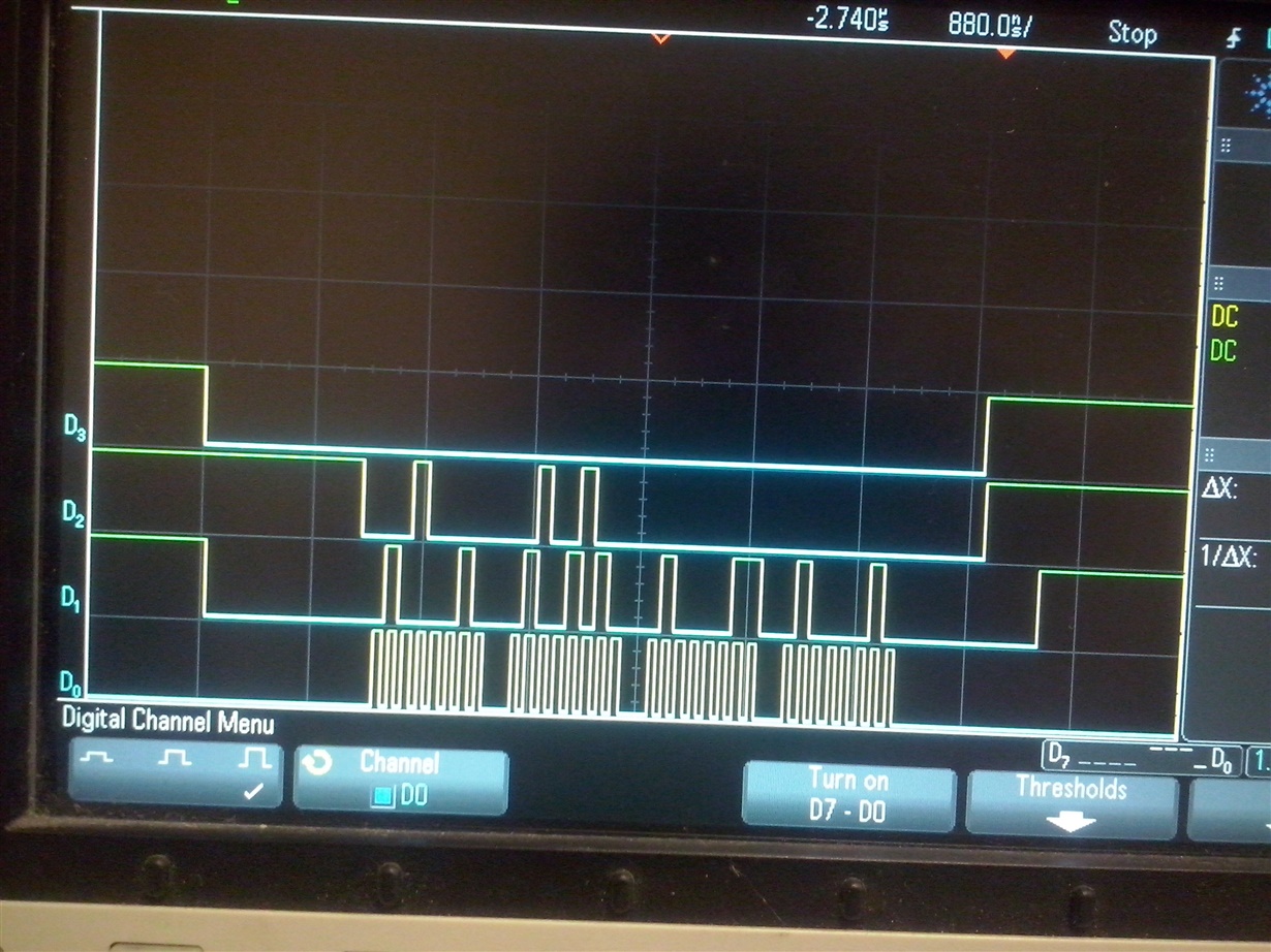
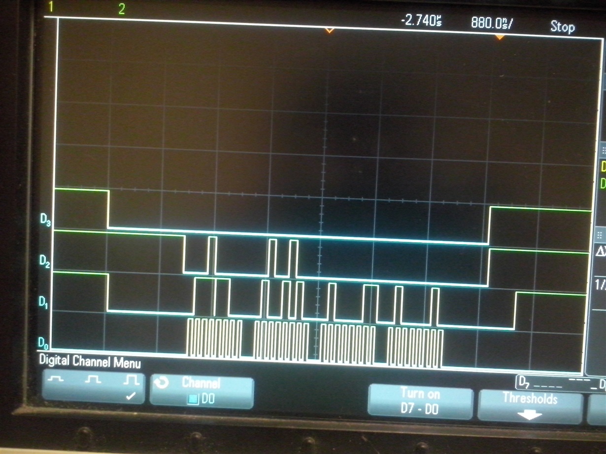
    oscilloscope signals using CS

    1st read


    2nd read

  • Hi,

    The SPI interface is, from hardware point of  view , a ring shifting register - what is in master is transferred to slave and vice-versa. But, the first byte sent, the command, is not processed or known until fully saved into internal buffer, so after that is parsed (decoded) and starting  with the second byte, you may have a wanted result.

    In other words, from software point of view, the first received byte is dummy and should be trashed and the second and followings could make a good result. The data sheet of your device specify the number of dummy bytes to be escaped/trashed before the good result. (IIRC that document is one of application notes specified by you in previous thread). So read the documentation again.

    Also, IIRC, your device need the last address byte to be sent first - little endian system - so after parsing the address into bytes you must start sending them from index 0, not 2. Am I correct?

  • Hello Petrei

    thanks for you response, really it helped me a lot.

    I didn't understand that part in the document, it is necessary make a flush operation Amit said, becouse the master sends a byte and the slave answers. the address bytes and the dummy byte answer a data trash after, the slave gives the good bytes, is it correct?

    and the document mention "send the MSB first" but the order of bytes is [2] first, [1] second, [0] last. So, I made the necessary changes in my functions and it works awesome! Using the Fss pin or any pin as CS it works very well, now I'm able to write and read any register

    thank you so much

    - Angel Nino

    sharing my SSI configuration:

    void ConfigureSSI(void)
    {
         MAP_SysCtlPeripheralEnable(SYSCTL_PERIPH_GPIOA);
         MAP_SysCtlPeripheralEnable(SYSCTL_PERIPH_SSI0);
    
         MAP_GPIOPinConfigure(GPIO_PA2_SSI0CLK);	//SCK
         MAP_GPIOPinConfigure(GPIO_PA3_SSI0FSS);	//CS
         MAP_GPIOPinConfigure(GPIO_PA4_SSI0XDAT0);	//Tx (MOSI)
         MAP_GPIOPinConfigure(GPIO_PA5_SSI0XDAT1);	//RX (MISO)
         MAP_GPIOPinTypeSSI(GPIO_PORTA_BASE, GPIO_PIN_5 | GPIO_PIN_4 | GPIO_PIN_3 | GPIO_PIN_2); //
    
         MAP_SSIConfigSetExpClk(SSI0_BASE, 120000000, SSI_FRF_MOTO_MODE_0, SSI_MODE_MASTER, 8000000, 8);
         MAP_SSIAdvModeSet(SSI0_BASE, SSI_ADV_MODE_READ_WRITE);
         MAP_SSIAdvFrameHoldEnable(SSI0_BASE);
         MAP_SSIEnable(SSI0_BASE);
    }

    // Read 32 bits
    void ft800mem_Write32(unsigned long ftAddress, unsigned long ftData32) { unsigned char cTempAddr[3]; // FT800 Memory Address unsigned char cTempData[4]; // 32-bit data to write cTempAddr[2] = (char) (ftAddress >> 16) | MEM_WRITE; // Compose the command and address to send cTempAddr[1] = (char) (ftAddress >> 8); // middle byte cTempAddr[0] = (char) (ftAddress); // low byte cTempData[3] = (char) (ftData32 >> 24); // Compose data to be sent - high byte cTempData[2] = (char) (ftData32 >> 16); // cTempData[1] = (char) (ftData32 >> 8); // cTempData[0] = (char) (ftData32); // low byte // GPIOPinWrite(GPIO_PORTN_BASE, GPIO_PIN_CS, 0); // Set chip select low while(SSIDataGetNonBlocking(SSI0_BASE, &pui32DataRx)); SSIDataPut(SSI0_BASE, cTempAddr[2]); // Send Memory Write plus high address byte SSIDataPut(SSI0_BASE, cTempAddr[1]); SSIDataPut(SSI0_BASE, cTempAddr[0]); SSIDataPut(SSI0_BASE, cTempData[0]); // Send data byte SSIDataPut(SSI0_BASE, cTempData[1]); SSIDataPut(SSI0_BASE, cTempData[2]); // SSIDataPut(SSI0_BASE, cTempData[3]); SSIAdvDataPutFrameEnd(SSI0_BASE, cTempData[3]); // while(SSIBusy(SSI0_BASE)); // GPIOPinWrite(GPIO_PORTN_BASE, GPIO_PIN_CS, GPIO_PIN_CS); // Set chip select high }

  • Hello Angel

    Advanced modes work differently from Legacy mode for the QSPI peripheral. In advanced mode the CS control is also handled by the peripheral and depending on whether you use the Advanced write or Advanced read-write operation, the requirement of flushing the RXFIFO may not or may be required.
  • Hello Amit

    seems what in this case was necessary if I understood the correct using from advanced mode, I hope to be correct. I'll continue make more probes.

    (comment: I'm practicing my english too, if I have any bad expression or incorrect word please tell me)

    Thank you

    -Angel Nino
  • Hello Angel

    You can refer to use model of the QSPI in the following TI Design

    www.ti.com/.../TIDM-TM4C129SDRAMNVM

    Where it is interfaced to a Serial Flash interface.
  • sharing my read function:

    unsigned int ft800mem_Read16(unsigned long ftAddress)
    {
        unsigned int ftData16 = 0;                                  	// 16-bits to return
        unsigned char cTempAddr[3];                                 	// FT800 Memory Address
        unsigned char cTempData[2];                                 	// Place-holder for 16-bits being read
        unsigned char cZeroFill = ZERO;
    
        cTempAddr[2] = (char) (ftAddress >> 16) | MEM_READ;         	// Compose the command and address to send
        cTempAddr[1] = (char) (ftAddress >> 8);                     	// middle byte
        cTempAddr[0] = (char) (ftAddress);                          	// low byte
    
    //    GPIOPinWrite(GPIO_PORTN_BASE, GPIO_PIN_CS, 0);              	// Set chip select low
        while(SSIDataGetNonBlocking(SSI0_BASE, &pui32DataRx));
    
        SSIDataPut(SSI0_BASE, cTempAddr[2]);                      		// Send Memory Write plus high address byte
        SSIDataPut(SSI0_BASE, cTempAddr[1]);
        SSIDataPut(SSI0_BASE, cTempAddr[0]);
        SSIDataPut(SSI0_BASE, cZeroFill);                    			// Send dummy byte
        SSIDataPut(SSI0_BASE, cZeroFill);
    //    SSIDataPut(SSI0_BASE, cZeroFill);
        SSIAdvDataPutFrameEnd(SSI0_BASE, cZeroFill);
    
        SSIDataGet(SSI0_BASE, &pui32DataRx);
        SSIDataGet(SSI0_BASE, &pui32DataRx);
        SSIDataGet(SSI0_BASE, &pui32DataRx);
        SSIDataGet(SSI0_BASE, &pui32DataRx);
        SSIDataGet(SSI0_BASE, &cTempData[0]); 				    		// Receive data byte
        SSIDataGet(SSI0_BASE, &cTempData[1]);
    
    //    while(SSIBusy(SSI0_BASE));
    //    GPIOPinWrite(GPIO_PORTN_BASE, GPIO_PIN_CS, GPIO_PIN_CS);    	  // Set chip select high
    
        ftData16 = (cTempData[1]<< 8) |                             	// Compose value to return - high byte
                           (cTempData[0]);                          	// low byte
    
      return ftData16;                                          		// Return 16-bits
    }

    Regards

    -Angel Nino

  • Hello Angel

    Please see the reference code for Advanced mode use. The above pasted code is not the correct model for advanced mode.