This thread has been locked.

If you have a related question, please click the "Ask a related question" button in the top right corner. The newly created question will be automatically linked to this question.

CCS/TM4C123GH6PM: Unable to trigger the ADC at desired rate

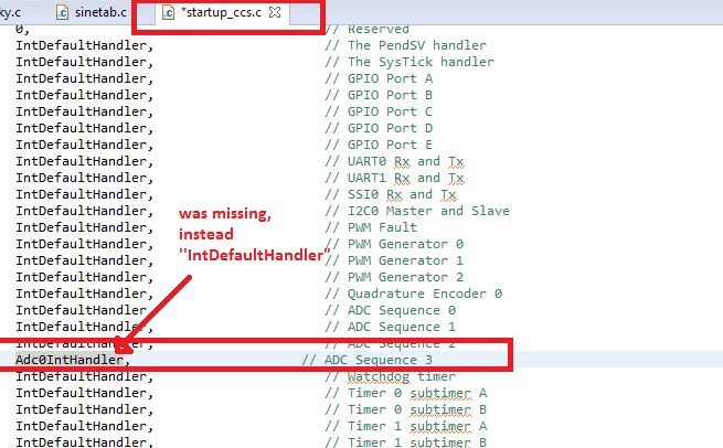
Part Number: TM4C123GH6PM

Tool/software: Code Composer Studio

Hi All,

I am trying to control the ADC triggering with CPU Timer.

My clock is set at 80MHz

"SysCtlClockSet(SYSCTL_SYSDIV_2_5 | SYSCTL_USE_PLL | SYSCTL_XTAL_16MHZ | SYSCTL_OSC_MAIN);"

And I am trying to trigger the timer int at 1MHz

"TimerLoadSet(TIMER0_BASE, TIMER_A, SysCtlClockGet()/80); "

SysCtlClockSet(SYSCTL_SYSDIV_2_5 | SYSCTL_USE_PLL | SYSCTL_XTAL_16MHZ | SYSCTL_OSC_MAIN);//Clock is set at 80MHz
    //SysCtlClockSet(SYSCTL_OSC_MAIN);


    //Initialize ADC
    SysCtlPeripheralEnable(SYSCTL_PERIPH_GPIOE); //Pin for ADC input
    SysCtlPeripheralEnable(SYSCTL_PERIPH_ADC0); //ADC peripheral
    SysCtlPeripheralEnable(SYSCTL_PERIPH_TIMER0);

    //Pins used for ADC channels
    GPIOPinTypeADC(GPIO_PORTE_BASE, GPIO_PIN_3); //set GPIO_E3 for channel 1
    ADCSequenceConfigure(ADC0_BASE, 3, ADC_TRIGGER_TIMER, 0); //sequencer 0
    ADCSequenceStepConfigure(ADC0_BASE, 3, 0, ADC_CTL_CH0 | ADC_CTL_IE | ADC_CTL_END);

    TimerConfigure(TIMER0_BASE, TIMER_CFG_PERIODIC);
    TimerLoadSet(TIMER0_BASE, TIMER_A, SysCtlClockGet()/80); //1MHz
    TimerEnable(TIMER0_BASE, TIMER_A);
    TimerControlTrigger(TIMER0_BASE,TIMER_A,true);

    ADCSequenceEnable(ADC0_BASE, 3);
    ADCIntEnable(ADC0_BASE, 3);

    while(1)
    {
    TimerEnable(TIMER0_BASE, TIMER_A);
    ADCIntClear(ADC0_BASE, 3);
    ADCIntEnable(ADC0_BASE, 3);

    //ADCIntClear(ADC0_BASE, 3);
    while(!ADCIntStatus(ADC0_BASE, 3, 0));

    ADCSequenceDataGet(ADC0_BASE, 3, &value);
    ADCIntDisable(ADC0_BASE, 3);

    if(i<2048)
    {
        data0[i++]=value;
    }
    }


Is this the right way to do it?

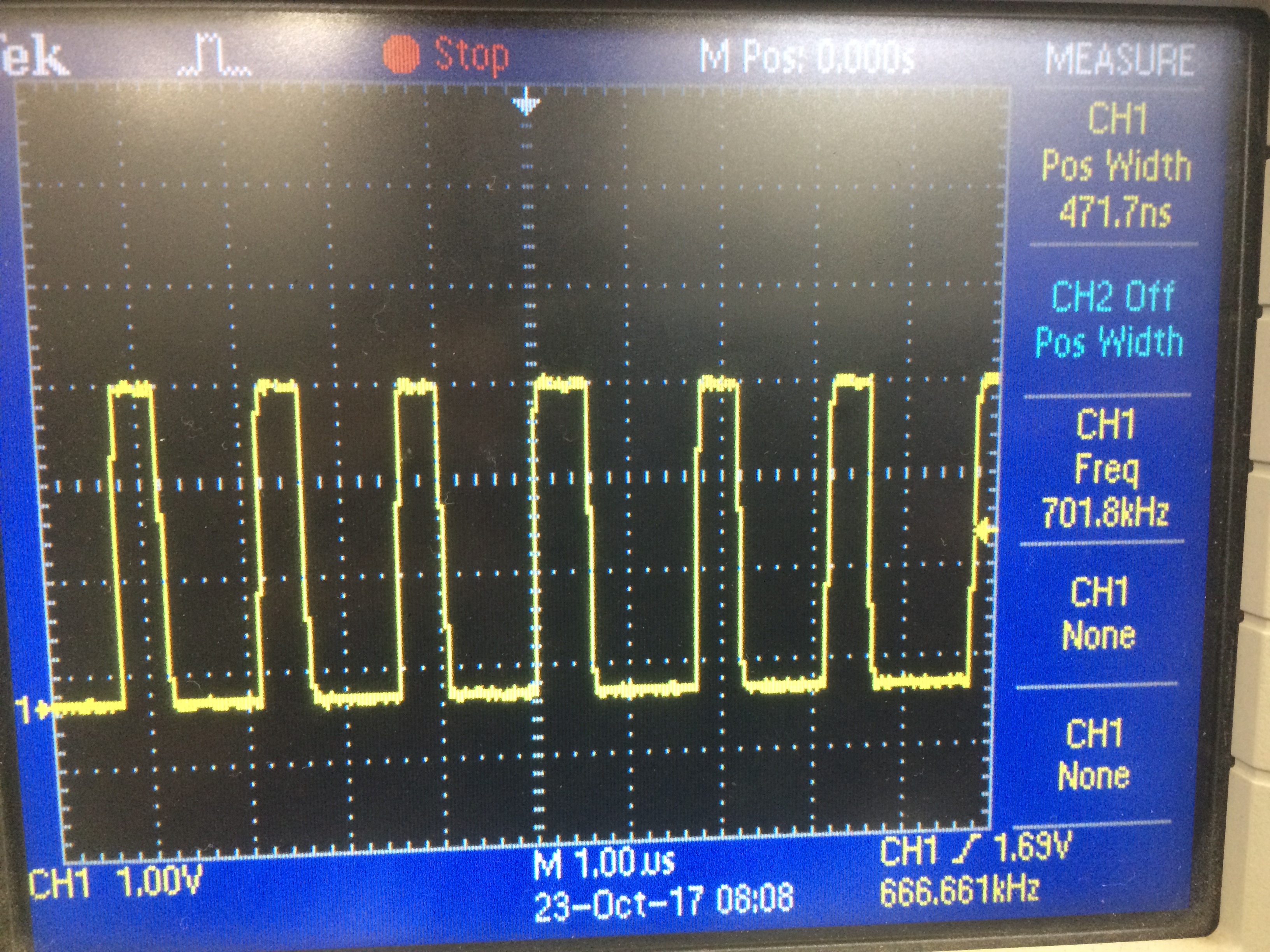
How can I check the triggering frequency of timer? 

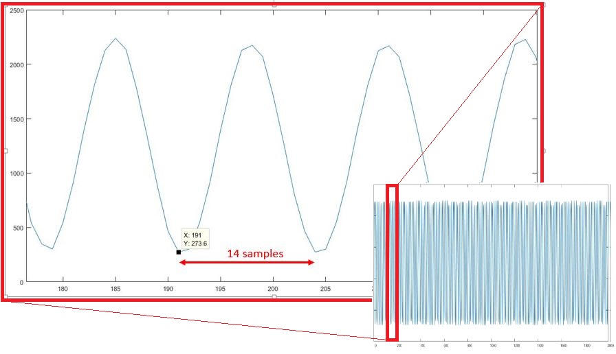
I am trying to fill an array of 2048 size with the ADC output - my ADC input is a sine wave generated by function generator of frequency 100KHz

So ideally the each sine period should have 10 samples. And so each period should take 10 places in the array. the complete 2048 array should contain 204 periods of sine "ideally". this is not happening.

I am confused whether I am triggering the ADC at 1MHz or not?:(

 
  • Hi Rohan,
    Since you want to use TIMER_A, you should change to TimerConfigure(TIMER0_BASE, TIMER_CFG_SPLIT_PAIR | TIMER_CFG_A_PERIODIC) and try again.
  • Hi Charles,

    I tried changing to "TimerConfigure(TIMER0_BASE, TIMER_CFG_SPLIT_PAIR | TIMER_CFG_A_PERIODIC)" but there is still no good result out of it.

    I am trying to acquire a 100KHz sine wave (for now) with the on board ADC (sampling rate 1MSPS - "TimerLoadSet(TIMER0_BASE, TIMER_A, SysCtlClockGet()/80)")

    I'm attaching a screenshot of the Graph of the data array in which I am storing the ADC out put. The data array is 2048 points.

    Please, suggest what might have gone wrong?

    Adding the source code below

    #include <stdint.h>
    #include <stdbool.h>
    #include "inc/hw_ints.h"
    #include "inc/hw_memmap.h"
    //#include "inc/hw_types.h"
    #include "driverlib/debug.h"
    #include "driverlib/adc.h"
    //#include "driverlib/fpu.h"
    #include "driverlib/gpio.h"
    #include "driverlib/interrupt.h"
    #include "driverlib/pin_map.h"
    #include "driverlib/rom.h"
    #include "driverlib/sysctl.h"
    #include "driverlib/timer.h"
    //#include "driverlib/uart.h"
    //#include "utils/uartstdio.h"
    
    
    uint32_t ADCNumOfSamples = 2048;
    uint32_t i=0;
    uint32_t c=0;
    uint32_t data0[2048];
    uint32_t Result[2000];
    
    uint32_t phase= 0;
    float x=1000;
    
    extern int QuadratureTable[360];
    extern float B[257];
    
    void Timer0IntHandler(void)
    {
        //i++;
        TimerIntClear(TIMER0_BASE, TIMER_TIMA_TIMEOUT);
    }
    
    void AquireON(void)
    {
        uint32_t value;
    
        TimerEnable(TIMER0_BASE, TIMER_A);
        ADCIntClear(ADC0_BASE, 3);
        ADCIntEnable(ADC0_BASE, 3);
    
        //ADCIntClear(ADC0_BASE, 3);
        while(!ADCIntStatus(ADC0_BASE, 3, 0));
    
        ADCSequenceDataGet(ADC0_BASE, 3, &value);
        ADCIntDisable(ADC0_BASE, 3);
    
        if(i<2048)
        {
            data0[i++]=value;
    
        }
    
        //return(value);
    }
    
    void main(){
    
        SysCtlClockSet(SYSCTL_SYSDIV_2_5 | SYSCTL_USE_PLL | SYSCTL_XTAL_16MHZ | SYSCTL_OSC_MAIN);//Clock is set at 80MHz
        //SysCtlClockSet(SYSCTL_OSC_MAIN);
    
    
        //Initialize ADC
        SysCtlPeripheralEnable(SYSCTL_PERIPH_GPIOE); //Pin for ADC input
        SysCtlPeripheralEnable(SYSCTL_PERIPH_ADC0); //ADC peripheral
        SysCtlPeripheralEnable(SYSCTL_PERIPH_TIMER0);
    
        //Pins used for ADC channels
        GPIOPinTypeADC(GPIO_PORTE_BASE, GPIO_PIN_3); //set GPIO_E3 for channel 1
        ADCSequenceConfigure(ADC0_BASE, 3, ADC_TRIGGER_TIMER, 0); //sequencer 0
        ADCSequenceStepConfigure(ADC0_BASE, 3, 0, ADC_CTL_CH0 | ADC_CTL_IE | ADC_CTL_END);
    
        //TimerConfigure(TIMER0_BASE, TIMER_CFG_PERIODIC);
    
        TimerLoadSet(TIMER0_BASE, TIMER_A, SysCtlClockGet()/80); //80MHz
        TimerConfigure(TIMER0_BASE, TIMER_CFG_SPLIT_PAIR | TIMER_CFG_A_PERIODIC);
        TimerEnable(TIMER0_BASE, TIMER_A);
        TimerControlTrigger(TIMER0_BASE,TIMER_A,true);
    
        ADCSequenceEnable(ADC0_BASE, 3);
        ADCIntEnable(ADC0_BASE, 3);
    
    
        //Enable ADC
    
        //uint32_t ADCCurrentIndex;
    
    
        while(1)
        {
    
            if(c==1)
            {
                AquireON(); //fill the 2048 aquire array {data0[]}
                if(i>2047)
                {
                    c=2;
                    i=0;
    
                }
    
            }
    
        }
    }

  • Might I suggest slowing everything down by a factor of 10 to start with and then speed it up towards you working speed?

    At full speed you've only got 80 clocks to convert, read and process the data before the next trigger is upon you. That's not a lot of time.

    Robert
  • Agree - and (of course) such SLOWING and SIMPLIFICATION is a clear illustration of the (always) INVALUABLE "KISS."

    Complication - brought on by such, "Overly Optimistic Starting Conditions" - most always DOOMS one to delay, frustration - too often FAILURE!

    Incremental - very well considered and managed (monitored) approaches - has long been proven to work best!    (had KISS been noted?)

    I would further suggest the generation of - rather than sine - a "Linear Ramp" - which makes each reading, "FAR MORE PREDICTABLE."    (easing the detection of errors!)

  • Hi Rohan, I have never used the TM4C123, But I have been working a while with analog acquisition using the TM4C129, which I believe is preety similar.

    For me the only way to achieve 1 MSPS rate or 2 MSPS with the TM4C uCs is avoiding using the CPU or processor convertion, I would recomend you to use DMA and control the sample rate with a timer. Here are some links, the first one is e2e post from me, where i was having similar problems to yours, at the end you will find a .c file of the code (watch out the startup file), but remember, this is using the TM4C129, maybe some considerations must be taken for your TM4C123. In the second link you will find a sound source localization proyect using the TM4C123 with DMA but without timer control, I hope this help you.


    https://e2e.ti.com/support/microcontrollers/tiva_arm/f/908/t/550008

    https://e2e.ti.com/support/microcontrollers/tiva_arm/f/908/t/550008

    https://www.hackster.io/graham_chow/acoustic-localisation-c7c8ab

  • Hi,

     -  Thanks for the info. I have reduced the number to check the maximum rate I can attain.

      - Yes I'm trying to work upon the "KISS" strategy.

     - The 1st link is not working and sorry I didnot understand the concept of uDMA (I will explore this topic in future), though I would like to stick to Timer trigger for now.

    void Timer0IntHandler(void)
    {
        uint32_t value;
    
        //i++;
        TimerEnable(TIMER0_BASE, TIMER_A);
        ADCIntClear(ADC0_BASE, 3);
        ADCIntEnable(ADC0_BASE, 3);
    
        //ADCIntClear(ADC0_BASE, 3);
        while(!ADCIntStatus(ADC0_BASE, 3, 0));
    
        ADCSequenceDataGet(ADC0_BASE, 3, &value);
        ADCIntDisable(ADC0_BASE, 3);
    
        if(i<2048)
        {
            data0[i++]=value;
    
        }
        TimerIntClear(TIMER0_BASE, TIMER_TIMA_TIMEOUT);
    
    }
    void main(){
    
        SysCtlClockSet(SYSCTL_SYSDIV_5 | SYSCTL_USE_PLL | SYSCTL_XTAL_16MHZ | SYSCTL_OSC_MAIN);//Clock is set at 40MHz
        //SysCtlClockSet(SYSCTL_OSC_MAIN);
    
    
        //Initialize ADC
        SysCtlPeripheralEnable(SYSCTL_PERIPH_GPIOE); //Pin for ADC input
        SysCtlPeripheralEnable(SYSCTL_PERIPH_ADC0); //ADC peripheral
        SysCtlPeripheralEnable(SYSCTL_PERIPH_TIMER0); //Timer0 Peripheral
    
        //TimerConfigure(TIMER0_BASE, TIMER_CFG_PERIODIC);
    
        TimerConfigure(TIMER0_BASE, TIMER_CFG_SPLIT_PAIR | TIMER_CFG_A_PERIODIC);
        TimerLoadSet(TIMER0_BASE, TIMER_A, 100000); //100KHz
        TimerEnable(TIMER0_BASE, TIMER_A);
        TimerControlTrigger(TIMER0_BASE,TIMER_A,true);
    
        //Pins used for ADC channels
        GPIOPinTypeADC(GPIO_PORTE_BASE, GPIO_PIN_3); //set GPIO_E3 for channel 1
        ADCSequenceConfigure(ADC0_BASE, 3, ADC_TRIGGER_TIMER, 0); //sequencer 0
        ADCSequenceStepConfigure(ADC0_BASE, 3, 0, ADC_CTL_CH0 | ADC_CTL_IE | ADC_CTL_END);
        ADCSequenceEnable(ADC0_BASE, 3);
    
    
        ADCIntEnable(ADC0_BASE, 3);
    
        for(;;);
    
    }

    Above given functions are the main and Timer0 ISR. But I am not able to trigger the ADC with this.

    As far as I understand there should be an ISR which will do the needful (putting the adc values in an array). this ISR should run everytime the Timer Interrupt is triggered (Hence I wrote the Timer0ISRHandler).

    With code snippets in the previous posts this was not implemented (as the routine was written in while(1)... loop), so I suspect it was a wrong approach.

    I am not sure where to define the ISRoutine so that when Timer0 interrupts the infinite idle loop to acquire adc results, this defined ISR should be executed and returned back to the idle loop.

    Kindly suggest

  • Hi Rohan the link has been updated, for your timer problem you should check if your interrupt service routine has been declared on the startup_ccs file of your project.
  • Rohan Chawhan said:
    As far as I understand there should be an ISR which will do the needful (putting the adc values in an array).

    Yes

    Rohan Chawhan said:
    this ISR should run everytime the Timer Interrupt is triggered

    Not really. It should run when the A/D interrupt is triggered. That will be some time after the timer interrupt. In fact you probably don't want a timer interrupt.

    Robert

  • Hey Can you point me towards a link or a resourec for what you suggested ?


    In fact you probably don't want a timer interrupt.

    I would help alot :)

  • Agreed - except for the fact that poster seeks, "Timer Triggered ADC operation."

    Is your sense that the (likely) "Periodic Timer - minus its ISR" - proves sufficient to, "Trigger the ADC" at "poster chosen, regular intervals?"

    Perhaps the "issue" lies w/in that, "Timer Trigger of the ADC?"      Does that "timer trigger" indeed develop a, "Timer Interrupt" - and if so - must that be cleared?    (so that further such, "Timer Triggers" occur...)

  • cb1_mobile said:
    Agreed - except for the fact that poster seeks, "Timer Triggered ADC operation."

    Is your sense that the (likely) "Periodic Timer - minus its ISR" - proves sufficient to, "Trigger the ADC" at "poster chosen, regular intervals?"

    Yes, the timer triggers the A/D conversion directly. I'm using it in that fashion.

    cb1_mobile said:
    Perhaps the "issue" lies w/in that, "Timer Trigger of the ADC?"      Does that "timer trigger" indeed develop a, "Timer Interrupt" - and if so - must that be cleared?

    I don't know that it does trigger an interrupt. It certainly doesn't need clearing. If the timer is set up to be periodic it simply triggers the A/D sequence on each period.

    Robert

  • Rohan Chawhan said:
    Hey Can you point me towards a link or a resourec for what you suggested ?

    Just the processor manual and the TIVAWare user guide. It's possible that there's a TIVAWare example but I don't know that there is.

    Robert

  • Thank you, Robert - it is likely that "poster's read & consideration of these two points" prove useful to "two" here...
    This "level of detail" proves a weakness to those employing ARM MCUs from different vendors - where "peripheral variance" may "rear its ugly head."
  • Hi All,

    Apologies for such late reply. I was not around due to some personal reasons.

    I am very happy to tell you all that the Issue is resolved now with all your help. I went through the whole issue again, and found 's post about the ISR routine not  declared in startup_ccs file.

    As the matter of fact "IT WAS NOT".

    The main code was pretty much the same.

    I had removed the Timer0 Interrupt handler as well "as suggested by many posters".


    I am able to trigger the ADC with the timer frequency which I could maximum attain upto ~700KHz (which I checked with a GPIO pin -> making it high and low to relate the entrance and exit of the ADC ISR)

    Thank you all for the help.

    Regards,

    Rohan

  • Rohan Chawhan said:
    I'm attaching a screenshot of the Graph of the data array in which I am storing the ADC out put.

    While your presentation of "ADC Trigger" is useful - it in no way matches the (required) detail - which your, "Graphic Screenshot" of 11 Oct 2017 provided.

    There ARE issues of significance - which are unlikely to be solved via "ADC Trigger" alone...      Is it not notable - that even after large passage of time - your post today "avoids" any "Graphic Screenshot?"    (as past supplied - and "so well" illustrated key aspects of your issue..)

  • Hi cb1_mobile (1830783)

    "My bad" - I didn't upload the screenshots of the results

    Below are the adc outputs for 50KHz and 25 KHz sine wave respectively for 700KHz sampling frequency

    Regards,

  • Thank you - (very) well done - and sure to be appreciated by many!

    Is it true that 700KHz was the fastest sampling rate you could (reasonably) achieve? (the results are greatly improved from your earlier cap!)

    May we ask the source of your "Graphic Presentation?" Is that part of CCS or an "outside graphing program" (i.e. Excel) and if "outside" - by what means did you introduce the captured ADC data into the graphic program?

    Again - applaud your persistence - and, "Just bask in your improved results!" (SO satisfying...)
  • Thankyou for your appreciation cb1_mobile (1830783)


    Is it true that 700KHz was the fastest sampling rate you could (reasonably) achieve? (the results are greatly improved from your earlier cap!

    Yes the image uploaded in today's post (the one with the square wave displayed on DSO) is what I got as maximum sampling rate, which was achieved by following snippet.

    //Configure TIMER0
        TimerConfigure(TIMER0_BASE, TIMER_CFG_SPLIT_PAIR | TIMER_CFG_A_PERIODIC);
        TimerLoadSet(TIMER0_BASE, TIMER_A, 0x1); //Fastest triggering with 0x1 counter
        TimerControlTrigger(TIMER0_BASE,TIMER_A,true);

    I saved the output in an array and used MATLAB for further improvements like collaging or overlapping. (same for all images uploaded till now)

    I use inbuild CCS Single time graph to see the output at run time but use MATLAB for presentations.

    Regards,

  • Excellent - both (crack staff - who have "abandoned ship" today) and this reporter thank you & appreciate your efforts.

    Further - your provision of Timer code & highlight of MATLAB & CCS' "Single Time Graph" may well encourage (others) to repeat your application - and may (possibly) yield "tweaks and/or improvements."
  • Hi Rohan, I am glad that you were able to solve the problem, now, I encourage you to try DMA, you will find that is really useful if you are going to use the uCs processor busy with other stuff.

  • Josue Pareja said:

    now, I encourage you to try DMA, you will find that is really useful if you are going to use the uCs processor busy with other stuff.

    Sure , after the project is done, I will surely look into "all the different ways" for FUN :)
    Again Thanks for your efforts. Cheers