This thread has been locked.

If you have a related question, please click the "Ask a related question" button in the top right corner. The newly created question will be automatically linked to this question.

DRV8316: Current Sensing Questions

Part Number: DRV8316

Hi,

The customer wants to calculate the current value flowing through U, V, and W when the motor is driven as the phase changes.

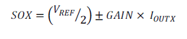
When operating the motor, calculate the IoutA value using the formula below.

Duty = 25%
U - SOA = 1.665V / Vref = 3.335V / gain = 0.15 / IoutA = -0.00125A

Duty = 50%
U - SOA = 1.665V / Vref = 3.335V / gain = 0.15 / IoutA = -0.00125A

Regardless of the Duty value of the motor, the same value is output to the SOA and Vref, resulting in the same IoutA value being calculated.

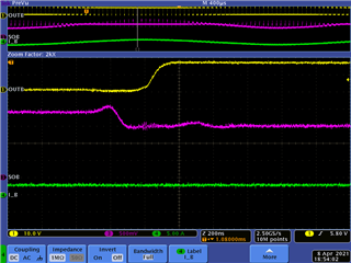
In this case, the voltage value of outA is large when Duty is high.

Is it normal for the motor to produce the same current value because the voltage output to outA is different, but the SOA and Vref values are the same?

In addition, SOA and Vref values change little regardless of motor operation and duty.

Please give us a guide on how to sense the current of each U, V, and W.

  • Hi Cho,

    SOx calculation is dependent on the amount of current (I_OUTx), GAIN, and VREF - not due to duty cycle. 

    To sense the current of U, V, and W, the MCU ADCs need to sample the CSA output signals (SOx) when OUTx is outputting a voltage (at the duty cycle). For instance, if the OUTx duty cycle is 80% at the time at 20kHz, I would expect the OUTx voltage to produce a measurable SOx voltage for about 40us (80% of 50us). After the CSA settles (settling time), the customer should sample the ADC to get an accurate current measurement. 

    Note that when using trapezoidal commutation, current will be the same during "on" states. Current is sampled in trapezoidal commutation during the BEMF periods (floating states) to detect zero crossings and provide sensorless trapezoidal commutation. 

    Otherwise, we see a lot of customers using sensorless-FOC or sinusoidal commutation using 2- or 3-phase CSA output feedback. 

    Attached is an image that shows OUTx and SOx using a sinusoidal algorithm. The zoomed in image shows the SOx voltage when there is positive current after the CSA settles. 

    Thanks,
    Aaron

  • Hello Cho,

    Do you need any further assistance on this thread?

    Thanks,

    Matt

  • Hi Matt,

    Sorry.
    I missed it, ended the thread.

  • Thanks Cho,

    Thanks,

    Matt