This thread has been locked.

If you have a related question, please click the "Ask a related question" button in the top right corner. The newly created question will be automatically linked to this question.

DRV8873SEVM: DRV8873SEVM DVDD&SPI communication

Part Number: DRV8873SEVM
Other Parts Discussed in Thread: DRV8873

Dear Expert ,

Good day!

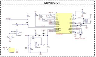
Our customer want to use the DRV8873SEVM to create the SPI communication .He had read the   thread link need to remove resistors in between MCU and motor driver IC

1 .https://e2e.ti.com/support/motor-drivers-group/motor-drivers/f/motor-drivers-forum/1004714/drv8873sevm-drv8873-spi-communication

2. https://e2e.ti.com/support/motor-drivers-group/motor-drivers/f/motor-drivers-forum/1004714/drv8873sevm-drv8873-spi-communication

But the SPI still  can not be recognized , In the design file of the EVM , DVDD pin connected to 5vdc , but he can not test the 5V on the board  , I also check the schematic , where is the 5V came from ? 

1. could you help me to confirm the design file in the DRV8873SEVM web-site , is it the schematic for the DRV8873SEVM?

2. could you advise any steps about how to check the EVM whether is working.

BR,

Leon.liu

  • on the schematic file DVDD pin on motor driver IC connected to 5vdc , does it correct?

  • Hi Guangyan,

    But the SPI still  can not be recognized , In the design file of the EVM , DVDD pin connected to 5vdc , but he can not test the 5V on the board  , I also check the schematic , where is the 5V came from ? 

    The 5V comes from the internal 5V regulator on the DRV8873. The DVDD pin is the output pin of the 5V regulator.

    1. could you help me to confirm the design file in the DRV8873SEVM web-site , is it the schematic for the DRV8873SEVM?

    Yes. The schematic files on the web are correct.

    2. could you advise any steps about how to check the EVM whether is working

    I see that you have removed all of the resistors between MCU and Driver. Are you only providing the external SPI signals? or are you also providing the nSLEEP voltage? If nSLEEP is 0V, then SPI communication will not happen since the device will be OFF. You need to provide 3.3V to nSLEEP to enable the driver.