This thread has been locked.

If you have a related question, please click the "Ask a related question" button in the top right corner. The newly created question will be automatically linked to this question.

DRV8353: High frequency oscillation

Part Number: DRV8353
Other Parts Discussed in Thread: CSD19536KTT

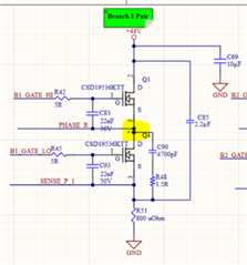
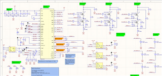
Hello, I'm here again with another revision of my DRV8353 circuit. The problem we're running into now is very high frequency (60-100MHz) oscillation on the switch nodes, seemingly unchangeable. For context, here's the schematic:

And on the switch nodes, we're seeing the yellow waveform below: 

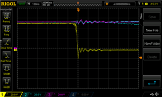
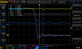
The VDrain node also shakes around, but not nearly as intensely (1V to 2V as opposed to -6V to -10V) We've tried everything we can think of to reduce the initial negative spike. TVS diodes are often too slow to cut this off. We tried putting a super-fast Schottky in parallel with the body diode (<10ns), but it didn't affect the waveform either. We tried increasing our snubber capacitors to 47nF. We then tried increasing the resistance of the snubber. We've tried a larger high side drain to low side source capacitor and a larger drain cap on the high side. It doesn't help. Slowing down the switching reduced the spike by a little, but as we increase the current, we still get close to -10V, which according to the datasheet is the maximum rating. We see this behavior on every switch node. What else can we try to do about this?

Separately, around 30A of motor current, this odd noise shows up on the switch nodes:

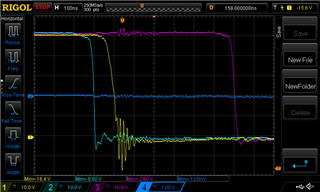
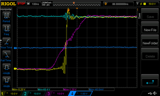
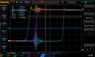
It doesn't happen every time we switch. It took a while to catch the particularly nasty ones such as the last one on the scope. I have to wonder, at that frequency, could this be due to our scope itself? Why is it only occasional? What can we do to handle noise that high frequency, when we also have to function up to 50A? The appearance of the envelope here is what confuses us most -- instead of having a peak and then ringing down, it increases and then decreases again.

  • Hi Alcor,

    Thanks for your E2E post - we are looking into this and will respond soon with feedback to your question and/or additional questions for info 

    Best Regards,

    Andrew

  • Hi Alcor,

    Wanted to give a quick update - we are still looking into this, and will try to get you a response early next week 

    Best Regards,

    Andrew

  • Thanks, I'll keep an eye on the thread.

  • Hi Alcor,

    Thanks for your patience - we aligned with the team today and have the below feedback/suggestions: 

    1. Oscilloscope: what is being probed on the board to measure SHx?
      1. for your suspicion about the scope itself, is your probe being placed on something like a test-point hook that might have a lot of inductance? 
      2. It may produce better results (less noise) if the MOSFET outputs are probed directly. (MOSFETs IC drain and source pins on SHx node) 
      3. also it may be worthwhile to see if any improvements come from different oscilloscopes/probe-tips.
    2. Layout: what does the layout look like for the output FETs? 
      1. is sufficient trace thickness being provided for the routing between gate driver and FETs, FETs SHx to motor, etc?
    3. Snubbers: For the snubber circuit's RC values, the performance of the snubber is less about how big the R and C is, but more about the targeted frequency to filter out. Please see the two attached resources below to target the noise observed in your first waveform. 
      1. usually the snubber part is left DNI first to assess the noise, then added in once you know what RC values to use. 
    4. Gate Drive current setting for your selected MOSFETs
      1. From the schematic, it looks like the FET part name is 'CSD19536KTT'
      2. attached a quick reference on how to calculate IDRIVE (gate drive current) based on MOSFET Qgd and desired switching speed
      3. if you use the lowest IDRIVE setting that meets your needs, how well does it filter out the noise? 

    5. VDRAIN node transients
      1. if Vdrain is having 1-2V shifts, this could possibly relate to the other problems.
      2. Vdrain is usually stabilized using bulk capacitance and decoupling caps (I see a few 620uF items on VM for bulk)
      3. need to make sure these are placed as close as possible to the VM IC pin 
      4. If operating at ~50V and 50A phase current, then this 2500W system might want more capacitance on VM to prevent voltage sags or spikes.
        (Rule of thumb from the high-power design app note is 2uF/W) 

    Link to some resources:

    - High Power motor driver design: https://www.ti.com/lit/an/slvaf66/slvaf66.pdf?ts=1631161862767

    - RC snubber FAQ: https://e2e.ti.com/support/motor-drivers-group/motor-drivers/f/motor-drivers-forum/991693/faq-proper-rc-snubber-design-for-motor-drivers

    - IDRIVE setting: https://e2e.ti.com/support/motor-drivers-group/motor-drivers/f/motor-drivers-forum/796378/faq-selecting-the-best-idrive-setting-and-why-this-is-essential

    Best Regards,

    Andrew