This thread has been locked.

If you have a related question, please click the "Ask a related question" button in the top right corner. The newly created question will be automatically linked to this question.

DRV8350: Help to review my design

Part Number: DRV8350
Other Parts Discussed in Thread: DRV8320,

Hi,

I'm developing a control board for a BLDC motor and in the last week I already burned almost 10 DRV's, cant understand wat's happening.

With no load the motor runs fine for some minutes, but sometimes when it stops, the DRV gets damaged and it starts overheating. I replaced the driver and everithing is ok until it gets burned again.

Based on this forum posts I already reduced the IDRIVE to 50/100 mA.

I'm using CSD18563 Mosfet.

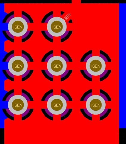
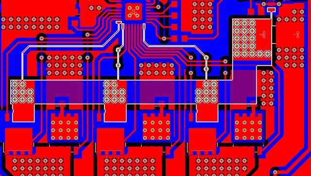
I share my schematic and layout for analyses.

DRV8350_SCHEMA

Thanks for the help

  • Hi Rui,

    We cannot access the site that you are linking to in your message. Can you attach the file by clicking Insert -> Inage/video/file --> click "Upload"

    Thanks,

    Matt

  • Hello Rui,

    I have two recommendations firstly:

    Please remove ALL thermal reliefs from GND, ISEN, PHASEA/B/C, VMOS, etc. This causes a huge amount of inductance in the high current path and normally results in a lot of ringing.

    There is a long trace from the low-side MOSFET source and the sense resistor. Ideally the sense resistor is placed as close to the low-side MOSFET sources as possible to minimize this path inductance.

    Please review our app note about high power design: https://www.ti.com/lit/an/slvaf66/slvaf66.pdf

    Thanks,

    Matt

  • Thanks for the help,

    I dont have thermal reliefs, ther must be some configuration in your eagle.

    I will review your recomendation about the long trace im my next version of design.

  • Hi Rui,

    As some additional comments, if you are using CSD18563 (60V), I would recommend using DRV8320 (65V) instead of DRV8350 (102V). DRV8320 will have lower IDRIVE settings built in where DRV8350 has a higher minimum IDRIVE. With CSD18563's QGD of 2.9 nC, even 50mA seems excessive because it results in a rise time of 58ns. We do recommend targeting 100-300ns rise time.

    Adding a diode in series with VMOS is dangerous in some aspects. If the motor acts as a generator the current cannot go back into the supply. You only have 4.7uF + 100nf + 10nF + 10nF + 10nF on the VMOS net which means in the event of current recirculation this node may increase dramatically and possibly cause damage to the system. You will need to observe the voltage of this node on an oscilloscope to be sure. We normally recommend bypass capacitance of 2uF per Watt of motor power (i.e. 100W motor -> 200uF capacitance).

    Please also confirm the voltage ratings of the following components:

    • C5 (should be at least 6.3V)
    • C6 (should be at least 25V)
    • C14 (should be the same rating as C13)
    • C9 (should be at least 25V)

    If you have not seen these resources, they may be helpful as well:

    Thanks,

    Matt

  • Hi Matt,

    We only go to the DRV8350 due to shortage of chips, it was the only one available, we buy 500. So, it's not an option to change to the DRV8320 now. 

    As for the diode I already bypassed the diode in the board(with a shunt) and we do have a dump resistor with a circuit that detects the overvoltage when the motor atcs like a generator. and inserts the resistor in the circuit.

    As for the capacitors they are all 50V rating.

    So, in short, do you think the main factor for the burned chips is the idrive settings?

    Do you think inserting resistors in the gate would slow down the rise time?

    Thanks,

  • Hi Rui,

    I think the IDRIVE setting and large path (inductance) to the sense resistor are the main causes.

    I would recommend adding series gate resistors to further decrease the gate drive current. I think 50/100mA is too much for those MOSFETs.

    Thanks,

    Matt