This thread has been locked.

If you have a related question, please click the "Ask a related question" button in the top right corner. The newly created question will be automatically linked to this question.

DRV8889-Q1: DRV8889_Q1 detect STL bit

Part Number: DRV8889-Q1
Other Parts Discussed in Thread: DRV8434S

Hello

      We use DRV8889-Q1 drive Stepper,when we  use self learning function ,but bit "STL_LRN_OK",never goes to high.then we set some value for "STL_TH",For example, we will "STL_TH" is assigned to 4. By reading the value of the register, the occasional STL can be set to 1, which can not be detected most of the time. We have put "STL_TH "value of th is tried from 0 to 255, and it is the same every time: the FAULT Status Register" STL" or DIAG Status 2  Register ““STALL””can not be detected as 1. However, our customer requires that 100%  can detect the“” STL“” setting as 1。
During the test, the stepper motor is as follows: when the stepper motor run normally, the operating current of the stepper motor is about 350mA. When locked rotor occurs, the current of the stepper motor is about 390ma to 420mA. I would like to ask how to improve the efficiency of seeing STL and achieve 100% detection? thanks。

  • Hello,

    We have an application note that might be helpful.  Link below:

    https://www.ti.com/lit/an/slvaei3/slvaei3.pdf

    When the motor is running normally, are you able to read back the TRQ_COUNT value from the DRV8889-Q1?  This would help to debug the issue and understand what a normal operation, no stall, value is for your motor.  

    Also, what is the DC resistance of your stepper motor?

    Regards,

    Ryan

  • Hello:
         I'm on a business trip these days.I'm sorry to reply today. I read TRQ_COUNT data form by read address 0X09 return data is 0, but if I read STALL_TH, read through the address, the read data is consistent with the written data.

         DC resistance  is :Coil resistance at 23 ℃      28.5Ω±8Ω

  • Hello,

    If you are really reading ZERO for TRQ_COUNT during normal operation (motor freely moving), I am definitely puzzled.  Which decay mode are you using?  You must use Smart Tune Ripple Control, or stall can't be reported.

    Regards,

    Ryan

  •   Hello

    The logic of locked rotor detection function of motor is as follows:
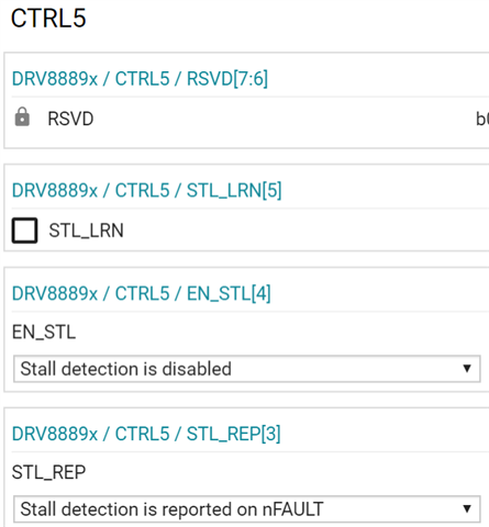
    a、Initialize ctrl5 register, STL_Rep = 0 reports stall error through register; EN_STL = 1 enable stall detection function;
    b、Ctrl3 register microstep_ Mode is set to: full_STEP_WITH_100_CURRENT;
    c、Ctrl1 register TRQ_DAC is set to current_100_PERSENTS
    d. Set CTRL2 register decaly to 0x07 and toff to 1, that is, smart_TUNE_RIPPLE_CONTROL.this data I have check again form read CRTL2 register,DECAY is 0x07;
    e、STALL_TH torque is assigned to ctrl6 register, now it is set to 25.
    f.  Read fault_STL bit of status register
    g. If STL is set, it indicates locked rotor and Ctrl4 register CLR_ FLT setting: clear stall setting at this time, and then judge whether it is in locked rotor state again.
    For the above register configuration, I read the configuration data of the register during operation. The read and write data are consistent. Sometimes I can read STL is 1 and TRQ_COUNT  value also is ZERO for many times. Please help analyze what's wrong. Thank you.

    The follow picture STATUS bit 0 is 1,because Stepper now is not run,So I have set CRTL2 bit DIS_OUT is 1,and at this config Stepper is not give out heat。

    .

  • Hello,

    Is the motor freely running when you check TRQ_COUNT?   What is the speed?  Can you send current plots showing current?  Can you try changing the micro-stepping mode to 32 ustep?

    Regards,

    Ryan

  • Hello:

       Yes,I have check  TRQ_COUNT at freely running data is zero,today I have test at micro-stepping mode is 32 ustep,it can read TRQ_COUNT  is 6 or 7,but stepper is shake and not run. if test  micro-stepping mode is1/2 or 1/4 ustep,stepper can run but read TRQ_COUNT  is zero at stepper freely running.

        stepper Nominal frequency is 333HZ,Nominal speed is 2.08 rpm ,Coil resistance at 23 ℃ is 28.5Ω±8Ω.

        thank you.

  • Hello,

    OK, at least you are getting a reading now.  How far along are you in your design and do you need automotive?  We have a device that has higher resolution on TRQ_CNT and a gain factor to amplify the value.  DRV8434S.  Would it be possible to consider this device?

    https://www.ti.com/product/DRV8434S

    Regards,

    Ryan

  • Rain,

    Several reasons could cause the stall detection function issue.

    1. When you enable the stall function, please set SRL_LRN=0 to disable the learning function. In learn mode, DRV8889 won't report the stall condition.

    2. According to https://www.ti.com/lit/an/slvaei3/slvaei3.pdf equation 5 and 6, a higher coil resistance (>10ohm) could cause a high IxR error to the TQR_COUNT. 

    3. To reduce or cancel the ixR error, the coil current 1st quadrant and 2nd quadrant waveform should be symmetric. Please check the output current to make sure the output current follows the ideal sinusoidal waveform.

    Regards,
    Wang Li

  • Hi Li

    Also update the motor spec, please help to check whether it could be driven by DRV8889Q1 and we need your confirm, thank you.

  • Hello, Zirui,

    The coil resistance is 28.5+/-8ohm in room temperature which is higher than 10ohm. The stall detection function may have an issue.

    Regards,

    Wang 

  • Hi Li,

    We have found some following description in the datasheet that we may not must need a lower than 10ohm motor:

    Now my customer is asking about why the motor could not pair with the DRV8889Q1 since it is difficult to find some motor coil resistance lower than 10ohm and do you mean if we use the 28.5ohm resistor the stall detection must not work? Since it is an urgent case could I loop you into customer e-mail so that we could discuss directly, thank you.

  • Zirui,

    10ohm was just from few previous test experience. There is no straightforward rule about the coil resistance. The 28.5ohm could work if the customer approves the stall function works in their system.

    The principle can be found in https://www.ti.com/lit/an/slvaei3/slvaei3.pdf. From equation 5 to 6, the I*R gives the TRQ_COUNT error if the 1st quadrant IxR is not cancelled by the 2nd quadrant IxR. A lower coil resistance has a small error. The stall function should work with a small coil resistance. The 28.5ohm coil needs the stall function validation before put on the production.

    BTW, the high resistance coil issue will be fixed in future devices.

    Regards,

    Wang Li

  • Thanks Li. Since both the motor driver chip and motor device are both determined by car OEM and could you please help to check why they could not use the stall detection function properly? Customer has done EMC test and need this stall detection function, hope you could help to analyze it and if you are OK maybe we need to discuss with customer via e-mail or have a WebEx meeting, do you think it is OK?

  • Zirui,

    Yes. Please send me an email to discuss it. Also, it would speed up the debugging process if they can have the output current measurement and have an EVM?

    The current waveform can check if the I*R can be cancelled. The EVM can allow us to check TRQ_COUNT register value in an analog signal (12.9mV/LSB of TRQ_COUNT).

    Regards,

    Wang