This thread has been locked.

If you have a related question, please click the "Ask a related question" button in the top right corner. The newly created question will be automatically linked to this question.

DRV8842EVM: Regarding Current Regulation

Part Number: DRV8842EVM
Other Parts Discussed in Thread: DRV8842-EP, DRV8842, , DRV8872-Q1, DRV8876

Hello,

This is a question regarding current regulation of DRV8842-EP.

We are now testing the current regulation function of DRV8842 on the evaluation board.

The test evaluation is below;
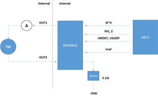
Target : DRV8842EVM

Rsense : 5.1ohm

Vref : 2.5v

Moter(TM) : L=43mH, R=24.9ohm

VM : 24v

We would like to check current regulation with adjustable Ichop.

Ichop and IN2 is constant. Ichop is 100%, IN2 is 0%.

In the pattern 1, IN1 is adjusted between 0% to 100%, and expected current value is 100mA.

Results of each test case is as a following;

Case 1: IN1=100%

Actual current = 138.4mA

Case 2: IN1=75%

Actual current = 162.5mA

Case 3: IN1=50%

Actual current = 99.6mA

Case 4: IN1=25%

Actual current = 99.3mA

Case 5: IN1=15%

Actual current = 99.6mA

Case 6: IN1=5%

Actual current = 31.9mA

Case 7 : IN1=0%

Actual current = 0mA

In these results, Case3 to Case7 could have operated current regulation, however Case1 and Case2 could not operate current regulation by Ichop.

Could you please tell me about configuration of correctly operated current regulation?

Thanks,
Sho

  • this is load connection image.

  • Kobori-san,

    This is an interesting case that I need to study more, but I have to ask why you are considering this device for such a low current application.  We have lower current devices that I think would be a better fit like the DRV8872-Q1.

    Regards,

    Ryan

  • Hi Ryan-san,

    Thank you for your reply.

    I answer to your question below,

    > I have to ask why you are considering this device for such a low current application.

    We would like to regulate Torque motor current. This current will be adjusted value between -100mA to +100mA from MCU instruction. A purpose of our circuit design control current feedback with only Driver IC. For example, we expect that Driver IC control at constant load current when the load impedance of torque motor change with such as deterioration.

    So, we doesn't have expected Itrip is constant such as DRV8872-Q1. On the other hand, DRV8842-EP is Ichop can be adjusted by i0 to i4 from MCU instruction.

    Is the Itrip of DRV8872-Q1 adjustable?

    Please advice.

    Thanks,

    Sho

  • Hello Kobori-San,

    I am sorry that you are experiencing these issues. 

    I have responded to your other post here:

    https://e2e.ti.com/support/motor-drivers-group/motor-drivers/f/motor-drivers-forum/1052834/drv8842evm-regarding-current-regulation-disagree-expected-value-and-actual-value

    I will conduct similar testing as you have with a smaller sense resistor. The low current, along with the large sense resistor could be why current regulation is not triggering at high duty cycles.

    Alternatively, I have been thinking of a solution that you could use in order to be able to digitally control current regulation with a lower current device. 

    The DRV8876 could be a potential solution:

    While the DRV8876 does not have digital pins I0-4, you could adjust current regulation by modulating VREF. You could use a microcontroller in combination with a DAC to be able to change VREF during operations, allowing you to adjust the current regulation threshold:

    https://www.ti.com/lit/ds/symlink/drv8876.pdf?ts=1637016122098&ref_url=https%253A%252F%252Fwww.ti.com%252Fproduct%252FDRV8876%253FkeyMatch%253DDRV8876


    Finally, does your application require automotive rating? If not I could start looking into other parts on our industrial chips that could be suitable.

    I will reach back once I have the results of my testing on the DRV8876; in the meantime let me know if there is anything else I can assist you with. 


    Best,

    Pedro Arango Ramirez

  • Hello Kobori-san,

    So far I have not been able to find an issue with the DRV8842 at higher currents. Would you be able to provide an output current waveform? It would be very helpful to understand the situation better.

    Additionally, have you given any thought into the DRV8876 solution?

    Best,

    Pedro Arango Ramirez. 

  • Hi Pedro-san,

    I'm sorry late reply.

    I can provide waveform data about this case.

    Please refer to attach zip file.

    DRV8842_EVM_TEST2.zip

    > Additionally, have you given any thought into the DRV8876 solution?

    A purpose of our circuit design is small circuit board, so we couldn't accept using external DAC such as DRV8876.

    Thanks,

    Sho

  • Hello Kobori-san,

    No worries on the late reply, I am happy to help. I think I might have found why the current regulation is not behaving as expected, the current regulation threshold of  -100mA to100mA seems to be too low for this device. More information below and possible fixes at the end of the explanation:

     The way in which the devices regulates current is described in section 8.3.3 of the datasheet:

    8.3.3 Current Regulation:

     The maximum current through the load is regulated by a fixed-frequency PWM current regulation (I believe this is around 50kHZ), or current chopping. When the H-bridge is enabled, current rises through the winding at a rate dependent on the DC voltage and inductance of the winding. After the current hits the current chopping threshold, the bridge disables the current until the beginning of the next PWM cycle. (This is from either the internal PWM or the Input PWM)

    It is important to note that this information needs to be paired with blanking time:

    8.3.4 Blanking Time

    After the current is enabled in an H-bridge, the voltage on the ISEN pin is ignored for a fixed period of time before enabling the current sense circuitry. This blanking time is fixed at 3.75 μs. Note that the blanking time also sets the minimum on-time of the PWM.

    We can see the combination of these effects happening on the Case 1 Waveform of TEST 2 that you uploaded:

    We can see that when given 100% duty cycle the outputs go high consistently for around 3.75 μs, as soon as that blanking time passes it immediately turns off because the current is higher than the current regulation threshold of 100mA. And it remains low until the internal current regulation PWM mentioned in section 8.3.3 (50kHZ) causes current to flow again. Effectively, this is the minimum on time that current regulation can achieve, therefore it can not effectively regulate current below this if driven at 100% PWM.

    Now I would like to explain why Case 2 possibly had an even higher current with lower duty cycle than Case 1. Here is the image you uploaded of case 2 at 75% duty cycle:

    Here we can see that there is an overall higher on time than in Case 1. If we look at the rising edge of a PWM cycle in the input we will see that the output will rise and stay on precisely for 3.75us (the blanking time) before turning off because the current is above the Itrip threshold. However the Input signal stays high for 20uS (50kHz) which cause the output to rise again due to the internal PWM for the current regulation clock. This is similar to the situation of Case 1.

    Where it differs is when the falling edge of the IN PWM signal appears. When it does the Output follows it and goes low and stays low until the next rising edge of the input PWM signal. When the Input PWM hits the rising edge, the output will enable and stay high only for 3.75us of blanking time before going low again and repeating the cycle. It is important to remember that the output only stays high for 3.75us because the current through the motor is still above the current threshold disabling the output whenever it can.

    This would explain why you are experiencing higher currents at duty cycles between 70%-99% than at 100%.

    Past that in cases 3 and 4 the current regulation seem to be working as intended. Turning off the outputs once the current is reached and only re-enabling it when the next rising edge of the input signal appears.

    SUMMARY:

    All of these problems stem from the fact that at this input voltage level the current is not decaying fast enough to stay in the sub 100mA threshold that you are targeting. Even the minimum on time for the output set by the blanking time and internal clock is causing too great of a current. Therefore, the main solution should be to find ways to minimize the current increase, and to maximize the current decay. Therefore, these are my suggestions:

    • If you haven’t already try changing the device’s decay mode to fast decay. This can be done to setting the decay pin to logic high, and should help increase the current decay.
    • If possible lower the input voltage so that current will rise slower through the windings.

    Please let me know if the fixes provided were helpful or if you have any questions about the operation of the system.


    Best,


    Pedro Arango Ramirez. 

  • Hi Pedro,

    Thank you for your support.

    My issue was resolved.

    Thanks,

    Sho