This thread has been locked.

If you have a related question, please click the "Ask a related question" button in the top right corner. The newly created question will be automatically linked to this question.

DRV8307: jitter issue

Part Number: DRV8307
Other Parts Discussed in Thread: DRV10987, DRV10987EVM, DRV10974, DRV10978, MCF8316A

Hi team,

Here's an issue from the customer may need your help:

The DC brushless cavity motor uses a photoencoder to measure speed and the pwm is controlled by the speed ring pid. At low speed 1.5r/s~6r/s, running with load will experience jitter and frozen.

Does this chip not drive the motor to steady operation at low speed? Or is there any possible cause?

Could you help check this case? Thanks.

Best Regards,

Cherry

  • Hi Cherry, 

    I don't think that the device should have major problems spinning at low speeds, as long as the hall inputs and other system-level inputs for this device are set up correctly. 

    Also a few more questions to help understand the problem better: 

    1. are you saying that the problem only happens at low speed? Is the system able to spin reliably w/o jitter/freezing at higher speeds? 
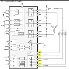
    2. are you providing hall sensor inputs to this device using the photoencoder? (see highlighted yellow pin inputs below).
    3. do you observe any fault signals on the nFAULT flag around the time that the motor stops spinning? 

    Thanks and Best Regards, 
    Andrew 

  • 1. Yes, it can rotate stably at high speed

    2. The three-phase Hall sensor pin of the motor is connected, and the photoelectric encoder is not connected to this

    3. When the motor stops rotating, the nFAULT has a fault signal

    Now I found a phenomenon. When there is jitter, I measured the waveform of the three-phase Hall input and the three-phase output and found that only one-phase Hall input has a square wave signal, but the three-phase output has square waves. In theory, shouldn't the three-phase square wave signal be output only when the three-phase Hall has square wave signals? I don't know if the processing logic of the chip is the cause of low-speed jitter.

  • Hi Kunzhi, 

    Thanks for the follow-up on this post 

    I will review further today and follow up shortly w/ some feedback/questions on next steps 

    Best Regards, 
    Andrew 

  • Hi Kunzhi, 

    Will need some more time to investigate this in detail - aiming to give a response by tuesday next week 

    Good to know that high-speed operation is fine. 

    Will need to investigate why there's an nFAULT signal while motor is stopped. 

    Will also need to check up on the commutation logic of this device in the datasheet for your last question. 

    Best Regards, 

    Andrew

  • Hi Kunzhi, 

    Thanks for your patience on this - 

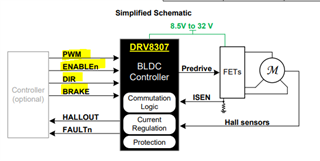
    So from looking at the device datasheet, it mentions that the 'DRV8307 is driven by a single PWM input and supports integrated commutation logic with three Hall sensor inputs.' 

    • this explains that the device operates on what is basically referred to as '1x PWM mode' since there's a single PWM deciding duty cycle and switching frequency of the motor driver outputs. Therefore whenever it sends signals to the gate driver outputs, it will send PWMs to all 3 phases separately. 

    Now moving onto the next points, 

    • The device has integrated commutation logic - so it's still expecting the three hall sensor inputs to feed in the proper square waves so that the DRV IC logic can determine what position the motor is in. In your case, since not all 3 of the hall inputs are providing square waves, this could explain why the DRV IC has trouble commutating the motor - and ends up with this 'jittery' effect you described. 
    • The 'FAULTn' pin description on page 5 says that it will pull low whenever it detects over-temp, over-current, or a 'rotor stall' 
      • page 18 describes 'rotor stall' in '7.3.11.6 Rotor Lockup (RLOCK)' as detecting a stall whenever HALLOUT doesn't have any transitions for 3seconds. 

    Conclusions: 

    • based on the information above, I feel like there is a problem with the hall effect sensors. 
    • if you have any filters impacting the hall sensors, maybe it is filtering out the signals at low speed - or there's possibly a bad connection between the hall sensor outputs and the DRV device pins. 
    • I would advise spinning the motor slowly by hand and seeing if the hall sensor outputs make sense 

    Please let us know if this information resolves your problem, and if you require any additional assistance 

    Best Regards, 
    Andrew 

  • I see that the datasheet describes that when the speed is stable, it is not necessary for all three Halls to provide square waves.

    I have no problem rotating the motor slowly by hand.And I have no problem controlling the motor with other drives.

    When I adjusted the parameters of the pi controller, I found that the larger the parameter, the greater the probability of jitter. I don't know if it is related to the pwm input.

    We suspect that there is a problem with the commutation logic of the chip, which leads to the wrong detection of the Hall sensor of the motor, and then the chip commutation problem caused by a problem with the pwm input.

  • Hi Kunzhi, 

    Thanks for the additional information - 

    Let me take some time to discuss this observation with my colleagues. 

    Will ask if there's any known limitation in this device operating at lower speeds, since the commutation is handled internally by the chip & not an external MCU 

    Best Regards, 
    Andrew 

  • Hi Kunzhi, 

    So I got a chance to discuss this e2e topic with my team today. Please see below responses. 

    1. Yes - when the speed is stable, the device will have this 'single-hall commutation' mode where it only needs 1xPWM input to generate 3xPWM output 
      1. also, the hall sensors are powered on and should still be outputting a signal to the DRV IC, even if the DRV device operates in this mode where Phase V,W signals are ignored/unnecessary.
      2. however, this only works at stable speeds. when the speed is not stable, the device needs all 3 Hall signals to work 
    2. This device does not have a speed-regulation control loop feature to compare actual motor speed feedback vs desired reference speed setting.
      1. because of this, the motor speed stability will have to be implemented by an external MCU 
    3. if you are seeing problems at lower speeds, then it could be a problem caused by non-ideal hall device placement and matching

    Question1: does this behavior happen on all DRV8307 devices, or just a few? Want to check if it's a systematic issue or a damaged device issue. 

    Question2: can you confirm if the hall sensor signals on all 3 phases are always sending signals from the Hall IC to the DRV IC during motor operation?

    • even if you are not using all 3 phases, there should still be square waves on all 3 hall signals if the hall is powered on and motor is spinning  

    Thanks and Best Regards,
    Andrew 

  • You said that when the speed is stable, it is judged according to the LOCKn signal? The 'single-hall commutation' mode have to be U-phase?

    The external MCU has a PI controller to keep the speed stable, but when the jitter suddenly occurs, the measurement finds that the LOCKn signal is still at a high level, which means that it is still running in single Hall mode, and at this time, it is also measured that only one Hall has a signal.

    1. Tried several DRV8307 chips have such a problem.

    2. The external MCU has a PI controller to keep the speed stable. All 3-phase Hall sensor signals are always sent from Hall IC to DRV IC in stable operation.

    However, when the jitter suddenly appeared, the measurement found that the LOCKn signal was still at a high level, which means that it was still running in single Hall mode, and at this time, only one Hall signal was measured.

    Question1: When the external mcu increases the parameters of the pi controller, the probability of jitter increases, which means that the input pwm causes the three-phase Hall to have two no signals. Why is this?

    Question2: When running with a fixed pwm input at low speed without load, jitter will also occur regularly. How to explain it?

  • Hi Kunzhi, 

    Thanks for the additional responses. 

    Will look into your comments about the LOCKn signal and give a response once I have a more detailed answer.

    Best Regards, 
    Andrew 

  • There are currently 2 guesses:
    1. At the beginning of the first jitter, the rotor of the motor should rotate back and forth, and the Hall sensor only has a signal of one phase, but the DRV IC thinks that the Hall is still commutating, and uses the single Hall mode, and the U-phase Hall signal is no problem. In this case, there is a problem with the output three-phase, and it starts to shake.

    2. At the beginning of the first jitter, the motor rotor should rotate back and forth, the Hall sensor only has one-phase signal, and the DRV IC needs to detect HALLOUT for 3 seconds in a row, and the single Hall mode is still used during these 3 seconds , and the U-phase Hall signal is no problem. In this case, there is a problem with the output three-phase, and it starts to shake.

    Conclusions:

    When the motor starts to shake, if there is a slight reversal caused by the load, the DRV IC still recognizes that the commutation is normal, but in fact the rotor position has been reversed, and then output 3xpwm according to the original logic, it will continue to shake, then in There is a problem with the commutation judgment logic of the chip at low speed.

  • Hi Kunzhi, 

    Those are some interesting points, and we will consider those possibilities in our further investigation

    Will give a response once I discuss a bit further within the team 

    Best Regards, 
    Andrew 

  • Hi Kunzhi, 

    I looked into this a bit further and have the below responses: 

    1. Question1: When the external mcu increases the parameters of the pi controller, the probability of jitter increases, which means that the input pwm causes the three-phase Hall to have two no signals. Why is this?
      1. AL: can you help clarify what the 'parameters' are in this statement? Are you talking about the duty cycle of the PWM input to the DRV device? 
    2. Question2: When running with a fixed pwm input at low speed without load, jitter will also occur regularly. How to explain it?

      1. However, when the jitter suddenly appeared, the measurement found that the LOCKn signal was still at a high level, which means that it was still running in single Hall mode, and at this time, only one Hall signal was measured.
      2. AL: just want to make a few clarifications here, so that we are in alignment about DRV device functionality 
        1. the DRV device is in 'single hall commutation mode' if LOCKn pin is logic LOW, to indicate that the speed is stable and only requires U-phase hall sensor inputs
        2. the DRV device is in 'standard hall commutation mode' if LOCKn pin is logic HIGH and requires all 3 hall sensors inputs to detect motor position and commutate the motor 
        3. Rotor Lockup 'RLOCK' is a separate feature for locked/stalled rotor detection described on page18 of datasheet. 
          1. the condition for RLOCK to happen is if there are no transitions detected on the HALLOUT signal for 3 seconds. 
          2. when this happens, BRAKE pin voltage will toggle high, and FAULTn pin voltage pulls low to disable motor output PWMs
          3. the device will then auto-retry recovery after a 5 second delay. 
        4. For fixed PWM input at low speed without load, Are you feeding in PWMs for all 3 phases U,V,W? 

    For the motor commutation algorithm, would it be possible to try out different start-up profiles? 

    • For example, can you start the motor at medium/high speed in the beginning, and then ramp down the speed and see if the jittery problem is still there? 

    Best Regards, 
    Andrew 

  • What I need is a mechanism to stop the motor without reporting an error when this happens, that is, when the Hall sensor signal is abnormal, the three-phase output is not commutated. As shown below: (0,1,2represent three-phase output, 4,5,6 represent Hall sensor signal)

    And the logic of DRV is at application of a sudden load that causes motor speed, the three-phase still has normal commutation output within 3 seconds, and finally stops the motor, As shown below: (0,1,2represent three-phase output, 4,5,6 represent Hall sensor signal)

    In general, the LOCK logic of the DRV8307 chip does not meet our requirements (that is, when starting, stopping or applying a sudden load that causes the motor speed to drop very rapidly, it is judged that the U-phase Hall sensor is abnormal for 3 seconds before reporting an error and stopping motor, but within 3 seconds of the abnormality, the three-phase still has normal commutation output)

    Do you have any chip model you can recommend?

    Thanks.

  • Hi Kunzhi,

    This is one of our legacy device and we do not provide much support to this device. What is the voltage and current rating of your application? I would recommend considering DRV10x family which is an integrated control solution. Can you check below E2E FAQ on DRV10x selection guide? If you find a suitable device that fits your application needs, then we can talk about tuning the DRV10x device.

    https://e2e.ti.com/support/motor-drivers-group/motor-drivers/f/motor-drivers-forum/918480/faq-drv10x-selection-guide

    Regards,

    Vishnu

  • Rated voltage 12V, rated current 0.45A.

    scenes to be used:
    1. It can run smoothly at high speed of 180~360rpm and low speed of 90rpm, without shaking during operation.
    2. If device need Hall sensor, it must be a three-hall mode, not a single-hall mode.

  • Hi Kunzhi,

    I would recommend trying out DRV10987 which might be a good fit for your application. This is a sensorless driver. Here's' the product page and the EVM page.

    DRV10987 product page: https://www.ti.com/product/DRV10987

    DRV10987EVM page: https://www.ti.com/tool/DRV10987EVM

    Please let me know if you have any questions. 

    Regards,

    Vishnu

  • Hi,

    At present, we have chosen the DRV10974 chip, whether it is also applicable and what is the difference between it and DRV10978?

  • Hi Kunzhi,

    You can see the differences in the E2E FAQ that I shared earlier. DRV10974 is a low voltage driver and can be configured only using external resistors. Also, the memory in DRV10974 is OTP (One time programmable) whereas the memory in DRV10987 is EEPROM.

    Regards,

    Vishnu

  • Hi, Vishnu

    • According to the online information, the non-inductive three-phase drive will be unstable at low speed compared with the inductive drive, but the scene I use is at low speed and the load will change during low speed operation, is the DRV109xx non-inductive three-phase drive suitable for me?
    • And DRV109XX does not have an Enable pin to stop the motor immediately. To stop the motor, you need to set the speed to 0, and then stop the motor slowly, right? I need to stop the motor immediately so it doesn't meet my needs?
  • Kunzhi,

    I'm not sure what you mean by non-inductive 3 phase drive. We recently released MCF8316A which has Field oriented control (FOC) algorithm integrated into the device. FOC has speed control loop which can can provide better speed stability (even at lower speeds) with change in load. Also this device has DRVOFF pin and Motor stop features which can be used to stop the motor quickly. 

    Here's the product page link: https://www.ti.com/product/MCF8316A

    Since we are switching our discussions to DRV10x and MCx, can you close this thread and open a new thread by clicking "Ask a related question" button at the top right of this page?

    Regards,

    Vishnu