This thread has been locked.

If you have a related question, please click the "Ask a related question" button in the top right corner. The newly created question will be automatically linked to this question.

DRV8350R: Brushless motor PCB not working

Part Number: DRV8350R
Other Parts Discussed in Thread: DRV8350

Hi Team,

Good day! Posting this in behalf of the customer. Here it is. 

I recently switched from using the DRV8350HRTVT to
the DRV8350RHRGZR on a brushless motor controller board.

I designed a board using the DRV8350RHRGZR to drive a brushless motor but
the motor is not spinning.

I supplied 15V to the 15V inputs on the schematic, 5V to the 5V input on
the schematic, and 3.3v to the PWM and DIR pins.
I measured the fault pin (pulled up to 5V) and it reads 5V. I measured the
DVDD pin and it reads 0V.


I am using a maxon EC 45 flat Ø42.9 mm brushless motor with hall sensors.

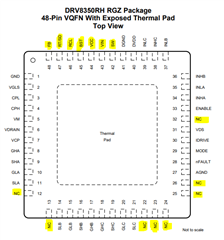
I followed the example circuit provided on the datasheet excluding the buck
converter (because I supply 5V from outside)

Here is the datasheet:
https://www.ti.com/lit/ds/symlink/drv8350r.pdf?HQS=dis-mous-null-mousermode-dsf-pf-null-wwe&DCM=yes&ref_url=https%3A%2F%2Fwww.mouser.com%2F&distId=26

I tried connecting the VM pin to the VDRAIN pin but the motor did not spin, and DVDD pin still reads 0V.


any help would be appreciated,

Best regards,

Jonathan

  • Hi Jonathan,

    Thanks for posting your question to the e2e forum - 

    I will take a look at this today and try to get you a response by tomorrow 

    Best Regards, 
    Andrew 

  • Hi Jonathan, 

    So I actually need a bit more time to finish reviewing the schematic more thoroughly to screen for problems.

    I got caught up with some urgent debug actions this week, but don't see any obvious problems from an intial glance 

    However, I do have some initial feedback for you that may help debug: 

    • Question: when you say that you moved from DRV8350HRTVT to DRV8350RHRGZR device, 
      • does that mean you had a working solution already for DRV8350HRTVT before? 
      • the diff between these two devices is just a buck regulator being integrated inside the IC, so the functionality of the DRV8350 chip itself should remain the same if you haven't made any changes to the other pins that aren't related to the buck regulator
    • If DVDD pin is reading '0V' then this might indicate some other problems with setup 
      • When you mention fault pin reads 5V, are you measuring close to the DRV IC, at the end of the pull-up resistor closer to the IC lead? 
      • I see that you have a 10k pullup to 5V, which is good. 
      • I am curious if DVDD is at 0V because of a separate fault condition, or if perhaps something's wrong with the way DVDD external cap is connected to the DRV IC. 

    Best Regards, 
    Andrew 

  • Hi Mark,

    Our customer need you to clarify something. Here is their response.

    I had a working solution already for DRV8350HRTVT.
    When I am measuring the fault pin, I measured the exposed pad of the pullup resistor.
    I switched ICs because DRV8350HRTVT was out of stock.
    It looks like I mislabelled pins such as VREF, SOC, SNC... as NC. Do any of these pins matter if I do not use the buck converter?
    Here is an updated schematic I am looking to try out. Do you see any problems here?

    Best regards,

    Jonathan

  • Hi Jonathan, 

    Thanks for the follow-up response. 

    Looking into this today and should be able to get you an answer within the next 48 hours 

    Best Regards, 
    Andrew 

  • Hi Jonathan, 

    Thanks for your patience. A few comments on the latest bits of info: 

    1. Unused Buck Regulator: 
      1. although I am not sure if this is going to cause a problem condition (like a Fault), I would suggest following datasheet advice for putting the buck into 'Shutdown' mode (see below): 
        1. since you currently have these buck-related pins floating, can't guarantee what the buck is doing to the system 
    2. CSA pins
      1. you mentioned a few pins that were mislabeled such as VREF, SOC, SNC, SPC, etc... 
      2. these are not for the buck regulator, they are for the current shunt amplifiers. 
      3. VREF should definitely be provided to the system. I believe it expects about 3-5.5V in order for the device to work properly
      4. The CSA inputs SPx/SNx for A,B,C phases should be taken care of accordingly if you are using those phases. Usually there's a shunt resistor between LS MOSFET source and GND, so that the DRV device can sense the motor phase current flowing through the low-side MOSFET. 
      5. If you do not use these properly, then the device could detect a false overcurrent condition & shut down the device. 
      6. If you are not planning on using these CSAs, then the best-practice is to ground the inputs (SPx, SNX) and then float the output (SOx) 

    Best Regards, 
    Andrew 

  • Hi Andrew,

    Our customer had modified their schematic based on your recommendations above. They would like to send this off to manufacturing to test it. Before that are there any issues with their schematic now? Kindly refer to attached file below.

    Best regards,

    Jonathan

  • Hi Jonathan, 

    Thanks for the update and understood - will take another look at their latest schematic to see if any issues stand out. 

    Best Regards, 
    Andrew

  • Hi Jonathan, 

    Thanks for your patience - I got a chance to review this in more detail with my team members. 

    Firstly, I wanted to mention that the correct pin diagram for your device variant is in the datasheet on page4: 

    Other than those two changes to handle the lack of CSAs and the non-use of the buck regulator, your schematic looks good to me.

    Best Regards, 
    Andrew 

  • Hi Andrew,

    Here is our customer response:

    I have noticed that I did not connect the DVDD pin from the chip to the DVDD label (Probably why I was reading 0V on it during testing). I will send this board out for manufacturing and testing. I will post if it works!

    Best regards,

    Jonathan

  • Hi Jonathan, 

    Thanks very much for your update and confirmation of the DVDD pin situation - 

    Looking forward to the next steps of your debug! 

    Best Regards, 
    Andrew 

  • Hi Andrew,

    Good day! As per customer, the new PCBs arrived and assembled the boards. The motor drivers worked! Thank you so much. I think the most likely reason for failure was the disconnected DVDD pin.

    Best regards, 

    Jonathan

  • Hi Jonathan, 

    Thanks very much for the update! 

    Glad to hear the customer issue is resolved as well 

    Best Regards, 
    Andrew