This thread has been locked.

If you have a related question, please click the "Ask a related question" button in the top right corner. The newly created question will be automatically linked to this question.

DRV8842: Current regulation

Part Number: DRV8842

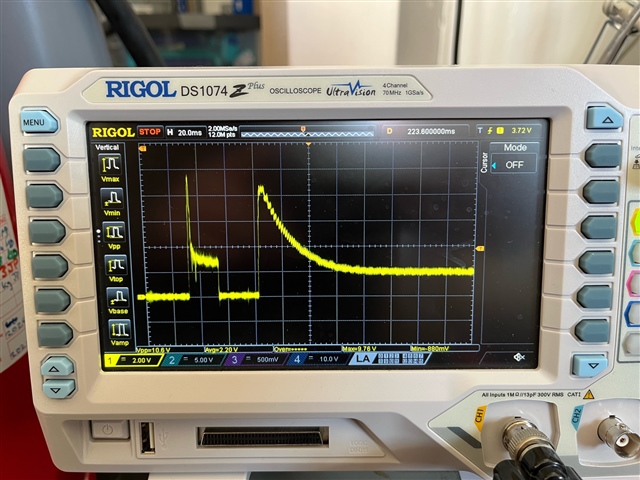
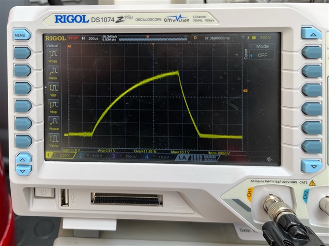
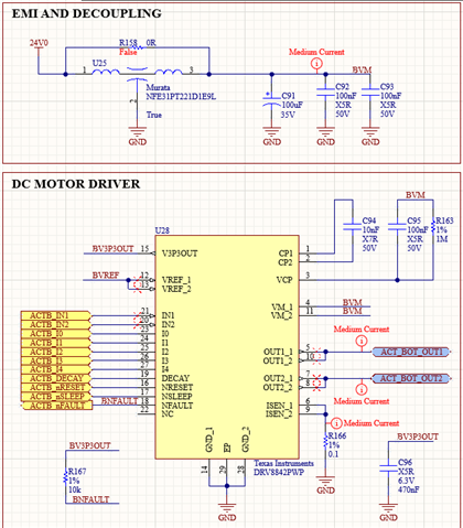
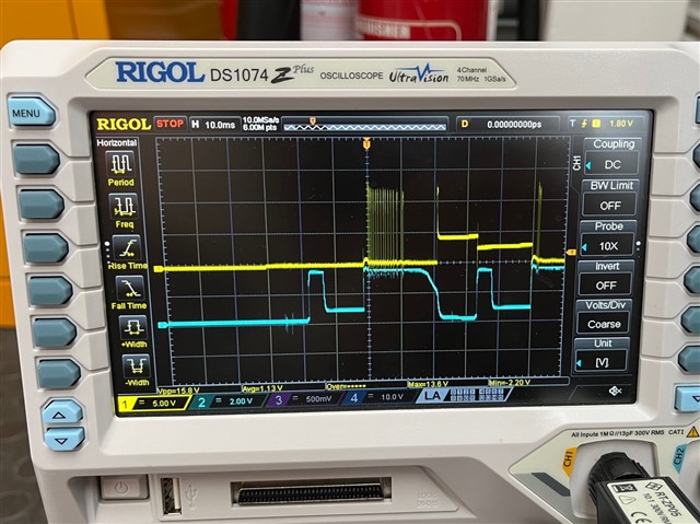
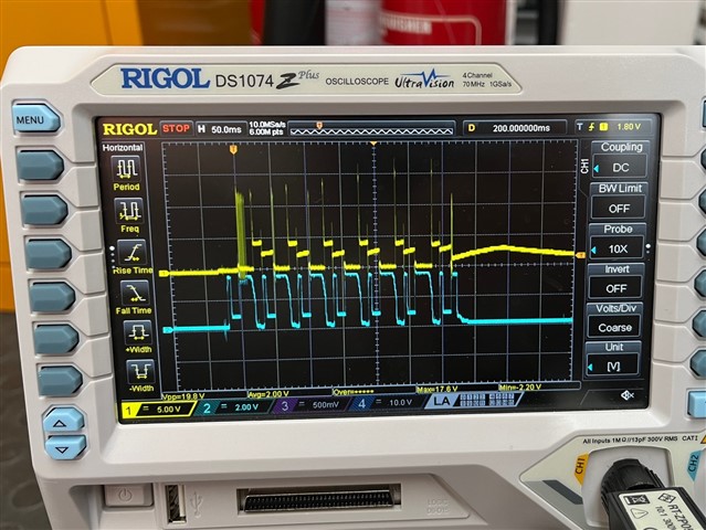
Hi, I'm using the DRV8842PWP to control a motor that only needs up to 3A, but the inrush can go up to 18A.

When I use the bench power supply (up to 3A) the motor works fine, but when I try with the embedded PSU (up to 20A) it triggers the faulty mode on the driver and the motor doesn't work.

I tried to limit the current going to VM, but it didn't work, I had to limit the current of the entire board to make the driver and motor work.

Apparently, the current regulation (I0-4) is not working for this purpose (we tried with different configurations).

Do you know what I can do to limit the inrush current without having to limit the whole board?

Thank you,

Camila

  • Camila,

    Do you have share scope captures of the current waveform into the load?  Are you using the EVM of your own board?  If own board, please share schematics.

    The nFAULT pin transitions low?  Is it a latched fault where you have to cycle nSLEEP to clear or does the part try to automatically recover?

    Regards,

    Ryan

  • Hi Ryan,

    Here is the photo of the current going to the motor (1V=1A) when an external current limiting is put on the source supply:

    Here without the external current limiting:

    Closeup of it:


    And here is the schematic of the driver:


    We have two motors with the same configuration, but one the I0-I4 is set to 100% of Ichop and the other to 50% (Ichop = 4.3A), neither of them works...

    When I connect the motor the nFAULT pin goes low but the nSLEEP stays high, I would need to disconnect it and press reset for the nFAULT to go back to high.

    Any idea what can be the problem?


    Thank you,

    Camila

  • Camila,

    Let me investigate closely and will respond in the morning.

    Regards,

    Ryan

  • Camila,

    Is it possible to add another channel to your scope and capture nFAULT pin response?  Would also be good to capture current level when nFAULT occurs.  It looks like the driver is hitting OCP which can occur if the current is ramping too quickly.  Is there any capacitance on your motor?

    Regards,

    Ryan

  • Hi Ryan,

    Yellow is the voltage on Out 1 and Blue the voltage on nFAULTY (both in relation to gnd):

    Do you know why is zero even before the sparks?

    When the motor is working (with the external current limiting) the nFAULTY is 3.3V as expected.

    Thanks,

    Camila

  • Camila,

    That is very bizarre behavior on nFAULT.  Do you have an external 10k pull-up resistor soemwhere on the schematic to 3.3V?  You mentioned the nFAULT is latched low before: 

    When I connect the motor the nFAULT pin goes low but the nSLEEP stays high, I would need to disconnect it and press reset for the nFAULT to go back to high.

    But that is not what I am seeing in your scope capture.  nFAULT is an open-drain output, so should pull hard to GND for a fault and release to 3.3V thru the pull-up resistor when everything is normal.

    Regards,

    Ryan

  • Hi Ryan,

    I only have the R167 10k ohm going from nFAULT to 3.3V (output of pin 15) as it shows on the schematic.

    I only recorded the changing parts with the oscilloscope, but if I measure with the multimeter I can read mV on nFAULT after trying to drive the motor.

    Cheers,

    Camila

  • Camila,

    Is your 3.3V supply stable?  Is your motor supply stable?  nFAULT should not bounce like this.  Need to start checking all the supplies to make sure nothing is dropping during this condition?

    Regards,

    Ryan

  • Hi Ryan,

    It should be stable, otherwise I would see weird behavior in other parts of the board, but I'll check it with the oscilloscope next week.

    Thanks,

    Camila

  • Camila,

    OK, thanks.

    Regards,

    Ryan

  • Hi Ryan,

    Sorry for the delay, I forgot to get back to you regarding the power supply stability.

    I tested it but without the full load and the power supply looked very stable (the board I have now can't drive the motor, I'll get back the one that I was using next week and then I can do this test again).

    I bought the DRV8842 evaluation board to try to isolate the problem and be able to debug more efficiently.

    And do you know if I can simulate the DRV8842 on LTSpice? I couldn't find a Spice model for it.

    Thanks,
    Camila

  • Camila,

    Thank you for the update.  Unfortunately, we do not have a model for this device.

    Regards,

    Ryan