This thread has been locked.

If you have a related question, please click the "Ask a related question" button in the top right corner. The newly created question will be automatically linked to this question.

DRV8328: question regarding the current sensing

Part Number: DRV8328

Hello,

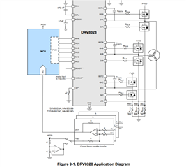
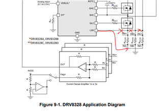
I'm designing a BLDC drive unit and I chose the DRV8328 three-phase gate driver. This gate driver has a single low side source pin (LSS) which needs to be connected to all the sources of the external low side MOSFETs. Now, I would have liked to sense the three phase currents independently, but is this even possible when the sources of the three low side MOSFETs are shorted? From the datasheet (see Figure 9-1) there seems to be the possibility of sensing the 3 phase currents with 3 separate resistors and 3 CSA but I don't really see how because the current will always flow on the parallel of the 3 Rsense, hence the 3 CSA will sense the same current, irrespective of the actual phase current. Is this correct?  

  • Hi Giorgio, 

    Thanks for reaching out via our e2e motor drivers forum. 

    I think your comment is correct that the shunts should be separate if there are 3 resistors, and I will sync up with the team about the diagram possibly being incorrect - 

    I have also linked the below resources to share on CSA configurations (1,2,3 shunt options). 

    Best Regards, 
    Andrew 

  • hi andrew and thank you for the answer. So, am I correct in saying that with the DRV8328 I can only go for the 1 shunt solution? 

  • Hi Giorgio, 

    Thanks once again for bringing this topic up in the e2e forum!

    Please refer to the answers below, and let us know if this resolves your question. Thanks! 

    So after discussing this further with my team, 

    1. for simplest implementation and optimal performance, we recommend that the DRV8328 device be used with 1-shunt CSA configuration 
      1. the 3 shunt setup in the 'application' diagram is incorrect and we will try to update the datasheet soon to correct that figure 
      2. For info on how to implement motor commutation w/ config for 1-shunt shared between 3 phases,
        please refer to the resources I shared above for help 

    2. as for the possibility of 3-shunt CSA implementation (separated, 1 per phase) 
      1. it may still be possible, but there will be some design modifications and trade-offs that you'll have to consider in your design. 
      2. Because there is only one LSS (low side source) IC pin, we can't have the LSS connected to high side node of each shunt resistor separately 
        1. The low-side VDS monitors for each phase depend on the LSS connection to the MOSFET power stage,
          so connecting each phase to one LSS would end up shorting together the shunt positive nodes anyway.  
      3. Alternatively, if you connect the one LSS pin to GND directly and keep the positive node of each shunt separated,
        1. you would be able to separate the shunt resistors to each have separate phase current paths 
        2. however, your LS VDS monitor's drain-to-source resistive path will now include MOSFET Rdson + Rshunt, whereas HS VDS monitor will only involve MOSFET Rdson (no Rshunt at HS). This means your VDS voltage trip threshold setting will have different effective current-trip thresholds at HS and LS VDS mointors.
        3. additionally, your secondary form of overcurrent protection (SEN_OCP) will now be disabled since LSS is always connected to GND and has no voltage differential. 

    Best Regards, 
    Andrew