- Ask a related questionWhat is a related question?A related question is a question created from another question. When the related question is created, it will be automatically linked to the original question.
This thread has been locked.
If you have a related question, please click the "Ask a related question" button in the top right corner. The newly created question will be automatically linked to this question.
Hello, we encounter the problem of motor stall when the motor is unloaded during the use of drv889. Please consult you about how to solve it. The specific configuration is as follows:
Motor model: MSRPC20B12
Register configuration: CTRL1:TRQ_ DAC is set to "0001"
Ctrl2:decay is set to "111"
CTRL3:MICROSTEP_ Mode is set to "0011"
CTRL5:EN_ STL set to "1"
CTRL5:STL_ LRN is set to "0"
CTRL6:STALL_ Th is not set, and the default value is "0xf"
Step foot control frequency: 500HZ
VREF voltage: 1.6V
Registers read: CTRL7:TRQ_ The default value of count is "0xff", and it is always "0" when the motor is running
Diag status 2: the value read by stall motor with high probability is "1"
Run the motor according to the configuration in the above figure, and read the motor stall when the motor is unloaded. Please help to see what the reason is, thank you!
MSRPC20B12_Data Sheet.pdfMSRPC20B12 F-T.pdf
Please refer the two files.
Close out of step detection, and the motor can rotate normally.
Sam,
It appears the winding resistance is 215 ohms. This is too high for stall detect to work.
https://www.ti.com/lit/an/slvaei3/slvaei3.pdf
Please see section 7.6.1
Regards,
Ryan
Dear Ryan,
My customer has changed the Motor type.
There are some questions about this project in the jpg below.

Ryan,
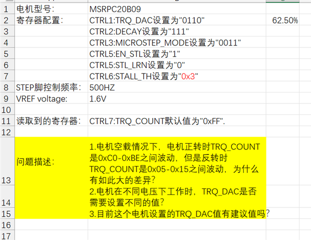
Motor model: msrpc20b09
Register configuration: ctrl1: TRQ_ DAC set to "0110"
Ctrl2: decay is set to "111"
CTRL3:MICROSTEP_ Mode is set to "0011"
CTRL5:EN_ STL set to "1"
CTRL5:STL_ LRN set to "0"
CTRL6:STALL_ Th is set to "0x3"
Step foot control frequency: 500Hz
VREF voltage: 1.6V
Register read: ctrl7: TRQ_ The default value of count is "0xff"
Problem Description: 1. TRQ when the motor rotates forward under no-load condition_ Count fluctuates between 0xc0-0xbe, but TRQ during inversion_ Count fluctuates between 0x05 and 0x15. Why is there such a big difference?
2. When the motor operates under different voltages, TRQ_ Does the DAC need to set different values?
3. TRQ set for this motor_ Is there a recommended DAC value?
Sam,
1) When you say "inversion_count", does that mean the motor runs in reverse? So, FORWARD the count is between 0xc0-0xbe, but REVERSE the count is between 0x05-0x15? There can certainly be a difference, but that is too large in my opinion. Are you keeping the STEP frequency static this whole time?
2) TRQ_DAC controls the regulated current in the motor. It is not necessary to adjust with changes in supply. But, in general, DRV8889-Q1 can detect stall if the voltage drop across the motor coil resistance is lower than the supply voltage. So, with higher supplies and lower current, you will get better results to stall detection.
3) This 100% depends on your load. I can't tell you a recommended value. You can only determine this thru experimentation in your system.
Regards,
Ryan
Ryan,
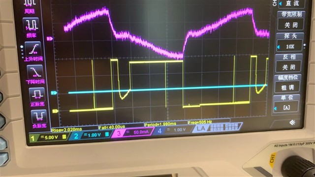
At present, the motor is noisy. The driving current and voltage waveforms are shown in the figure. Is there a recommended driving waveform? What is the relationship between the driving waveform and the internal resistance and other parameters of the motor?
By the way,i am sure i am keeping the STEP frequency static this whole time.So what should i do about the gap betweenn FORWAR count and REVERSE count ?Thanks a lot.
Sam,
What is your supply voltage? Motor speed? Does waveform get better with higher voltage or lower speed?
The resistance of your motor, 215 ohms, is very high. This means IR losses are high over load and it is difficult for the DRV8889-Q1 to properly regulate current.
Regards,
Ryan