This thread has been locked.

If you have a related question, please click the "Ask a related question" button in the top right corner. The newly created question will be automatically linked to this question.

DRV8350R: Some problem about the TVS diodes between G-gate and S-gate in the lowside

Part Number: DRV8350R

hello  Ti:

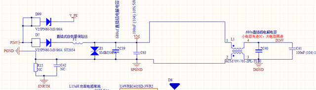
   we learn the the TVS diodes can help with negative transient spikes.So we add a SMF15CA.You can my schematic diagram.

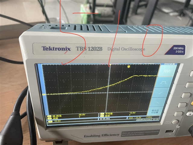
When I get my pcb.,I test it .The motor cann't run normally .Even one mosfet burned and one mosfet is shorted (g to s).But  I

remove these diodes,everything goes well.Since that we have test our last version pcb for months which didn't have these 

TVS diodes and  our idrve is the smalles value.So I am sure that the TVS diodes is the reason.

    Is my model selection wrong? Will zener diodes or  one-way TVS  be better? 

    Looking forward to your reply


1016.Motor.pdf

thanks

shengzhong

  • Hey Shengzhong

    I will consult the team and aim to provide feedback by Wednesday of next week.

    Best Regards,

    Akshay

  • Hey Shengzhong,


    Thank you for your patience.


    The TVS diodes being used at the moment is not protecting from negative transients since it is 15V rated. The GLx cannot be lower than -5V transient so this diode will not protect from negative transient. The bidirectional TVS diode being used at the moment will only protect against positive transients.


    You could add a gate resistor to further lower your gate drive current, as lowering gate drive current will help mitigate negative transients.


    In the meantime, I can consult my team for more information on this issue.


    Best Regards,

    Akshay

  • Hello  Akshay:

       Thanks for your reply.I am not sure weather there is a negative trainsient.I only use this for preventive effect .So it makes me puzzled that how this  TVS destroy the mosfet?Make it switch faster or slower?

      You say we need add a gate resistor. Do you see my schematic diagram? I have add a 510Ω and our rise time is 250 ns.Do you means if I add there is no negative transients ,the TVS is not necessary for my pcb?  I add the waveform before I add the TVS.

     Waiting for your reply.

    Best wishes

    shengzhong

  • Hey Shengzhong,

    I will consult my team and provide feedback by early next week.

    Thank you for your patience.

    Best Regards,

    Akshay

  • Hey Shengzhong,


    Based on the waveform provided I do not see a negative transient, therefore I do not think you need a protection against negative transients. You can add a unidirectional TVS diode between GLx and SPx rated between 15-18V for suppressing positive transients.


    Hope this offers some clarification.


    Best Regards,

    Akshay

  • Hello Akshay : 

              OK. But can you tell me the reason why the TVS will lead the damage? I am afraid that if I add the unidirectional TVS diode between GLx and SPx,the mosfet will be broken again .I only made ten pcb.

    thanks

    shengzhong

  • Hello Shengzhong,


    I would like to know whether the different grounds you have (DGND, SPGND etc.) are connected with each other using a net tie or a 0 Ohm resistor. If they are not, I recommend connecting them and seeing if the issue persists. This would help diagnose the issue.


    Also, I would like to make a correction to the previous reply. If you decide to add a unidirectional TVS diode, then it has to be between GLx and ground.


    Best Regards,

    Akshay

  • Hi Akhay:

          I send the picture about the DGND and SPGND(PGND).There is a common mode choke between  PGND and DGND. But reference ground of these drive chip like drv  ,mosfet is SPGND.And some sample signal ,we use DGND.So you can see  the SCH I send before,I add

    the two-way TVS between GLX and SPGND(PGND).

    thanks

    shengzhong

  • Hey Shengzhong,

    I will aim to provide feedback before the end of the week.


    Best Regards,

    Akshay

  • Hey Shengzhong,


    I have discussed the issue with my team and we noted that the bidirectional TVS diode will not help with suppressing negative transients. You want the diode to conduct if there is a negative transient. GLx will have to dip to -15V transient for the diode (an unlikely event) to conduct with a bidirectional TVS diode.

    We recommend implementing a diode in the following manner:

    We are not entirely sure why the TVS diode is causing the damage, so we could suggest some testing to be done to help diagnose the issue. However, you do run the risk of potentially damaging the board.


    Please let me know if you are interested in this approach and I can suggest the testing approach.


    Best Regards,

    Akshay

  • Hello Akshay,

           Thank you for your reply. Yes,after my testing our system with this board.I can use one pcb to test adding  unidirectional TVS. I have got a modle of TVS  SMF18A. I will tell your the result after my test.

    thanks

    shengzhong

  • Hey Shengzhong,


    For the unidirectional diode we would recommend a diode rated between 15-18V.


    If you wish to test the bidirectional diode on potential reasons for failure, we would like to obtain waveforms of SHx, VGS, voltage across bidirectional TVS diode, nFault and INLx.


    Best Regards,

    Akshay

  • Hey Akshay :

           I am sorry I didn't get the waveforms of those. When I added  these TVS (SMF18A) and sent the run order.The motor just run for a while .And the power get into the protection state . I found that the mos is shorted. I decide to remove the TVS although I don't found the reason.Maybe the tvs make the switch time of the mos too long  so that  the upper and lower Bridges are conducting at the same time?But I didn't measure this .When I need know this , I'll take risk to do this again but at present the problem makes me puzzled a lot.Anyway , I have known that it's not a question of TVS slection,right?

    thanks

    shengzhong

  • Hey Shengzhong,


    The waveforms might help explain if the issue we are seeing is due to a selection problem of the TVS diode, as we would be able to see how the TVS diode is operating and its effect on the outputs.


    Best Regards,

    Akshay