A related question is a question created from another question. When the related question is created, it will be automatically linked to the original question.
If you have a related question, please click the "Ask a related question" button in the top right corner. The newly created question will be automatically linked to this question.
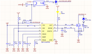
The passive component values should be rated for at least 10% higher voltage than the peak voltage they will see. For a 28V system, I would use 50V rated capacitors for items around the VIN. Of course logic-related passive components can be rated for just 10V if they will never see higher than 5V.
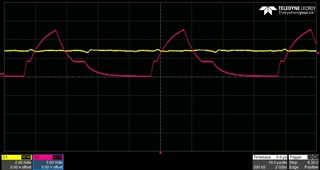
Please check the scope screen with the passive component values. After few seconds, MOSFET is getting hot, nearly 130C Degree. There is no problem except mosfet's temperature.
Can you post your full schematic for us to look at?
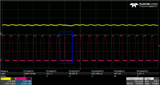
One thing you can try to reduce the temperature is by reducing the switching frequency. can you try to reduce the PWM frequency by adjusting Rosc. Test it at 1000Hz and measure the temperature. Does it go down?
By the way, this written values applied to DRV110EVM board. I'll test the reducing PWM. I'll let you know the test result. Also I have custom designed board, please check the values & schematics for same application. In custom board, with these values, MOSFET is burning is several seconds.
I fixed the MOSFET temperature problem with changing the MOSFET with lower gate capacitance. Also I decreased the PWM freq. I just have abnormal gate drive signal sometimes as I mentioned above.
The abnormal gate drive signal is an artifact of the hysteresis controller this device implements for current control - see 7.3.2 PWM Current Control. It is nothing to worry about. This device has a fixed frequency (25kHz). It sensed the current was too high right before the new on-cycle, so immediately turned off the output to limit the current back to the desired level.