This thread has been locked.

If you have a related question, please click the "Ask a related question" button in the top right corner. The newly created question will be automatically linked to this question.

DRV8825: Equipped with your company's stepping motor driver (model: DRV8825) I am designing a printed circuit board, but the stepping motor vibrates.. If you have any advice, please let me know.

Part Number: DRV8825
Other Parts Discussed in Thread: DRV8434

Hi,team,

My customer asked a question ,please help answer it,thank you.

Equipped with your company's stepping motor driver (model: DRV8825)
I am designing a printed circuit board, but the stepping motor vibrates.
A problem has occurred.

If you have any advice, please let me know.

The customer was quite anxious to solve the problem and needed sincere suggestion.

Please note that the attachment is the test report.

Best Regards,

Katherine.TI製ステッピングモータドライバ不具合報告(20221216).pdf

  • Katherine,

    That is a nice report.  Couple of questions:

    1)  When driving, is there an acceleration period before motor reaches the final speed?  Does vibration occur during this period or once motor reaches final speed?

    2)  Have they tried using micro-stepping modes to see if that improves the vibration?

    3)  I saw they swapped PCB/components.  Did they also try with different motors to see if vibration follows motor...possibly?

    4)  Can the customer please share the date code of the units with vibration vs. the units with no vibration issue?  A picture of the top of the package is what I need.

    Regards,

    Ryan

  • Hi,Ryan Kehr

    Thank you for your reply. I will convey your comments to the customer and look forward to your follow-up reply.

    Regards,

    Katherine

  • ライアン・ケール様

    レポートを作成しました桂川電機株式会社の小泉と申します。
    御世話になります。

    この度はお忙しい中、ご返答頂きありがとうございます。

    御連絡頂きました4項目について確認しますので
    少し御時間を頂けます様お願いします。

    小泉

  • Hi,Ryan Kehr

    The person who replied to the post below is my customer, who is confirming the fourth item.

    Please wait a moment, and look forward to your follow-up reply.

    Thank you very much.

    Regards,

    Katherine

  • Katherine,

    Any update on this?

    Regards,

    Ryan

  • Mr. Ryan Kehr

    The following text is sent on behalf of customers:

    TI製ステッピングモータドライバ不具合報告(20221221).pdf
    I am very sorry for the late reply.

    I answered your question, so please check the report.


    Koizumi

  • Hello,

    For #4, those are both valid date codes, so no issue there.  

    It looks like there is just some marginality in the design and the driver is going into a HIZ state and causing the vibration.  

    Can you try 1/2 step or even 1/4 step?  Increasing VREF will also increase current to maintain higher torque under micro-stepping.

    Regards,

    Ryan

  • Mr. Ryan Kehr

    It is said that the driver will be in HIZ state, but are there any conditions for it to be in HIZ state?

    Is it possible to vibrate if parts such as bypass capacitors are not placed correctly?

    I will check the 1/2 step and 1/4 step, so please give me some time.

    Koizumi

  • Hello,

    I would do the following:

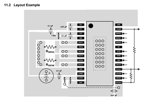
    - review pcb layout, ie. connections between grounds, there are 3 different grounds: P_GND, AVSS and ground of DRV8825,

    - check with an oscilloscope AVREF/BVREF against DRV8825 ground pins when the problem happens,

    check with an oscilloscope VM voltages against DRV8825 ground pins when the problem happens,

    - check two phase currents at the same time and see how currents behave in both phases,

    - try mixed and slow decays, and see if they change the situation,

    - using slow decay I would change slowly step frequency from 0 to around 2000Hz and identify any motor resonances in that range.

    Regards,

    Grzegorz

  • Mr. Ryan Kehr

    Thank you for pointing this out.

    I thought that the layout of the PCB was bad, so the DRV8825
    Change the board to make the layout according to the datasheet.

    The three GNDs are designed as follows.

    P_GND: GND to feed the sense resistor
    AVSS: GND for AVREF and BVREF
    ground of DRV8825: DRV8825, GND for decap of VMA and VMB

    Koizumi

  • Hello,

    Are all the GNDs connected together near the IC?  

    The vias for the sense resistor connect to the PowerPad vias (under the device) on the bottom side of board.

    Regards,

    Ryan

  • Mr. Ryan Kehr

    Although it is connected nearby, the bypass capacitors of VMA and VMB are mounted on the back side through vias.

    The sense resistor is also mounted on the back side through vias.

    I thought the layout was bad, so I will change the layout.

    Koizum

  • Koizumi,

    OK, you definitely want to minimize the inductance in the sense path.  

    However, if you are changing layout, could you consider a newer device in our portfolio?  

    https://www.ti.com/lit/ds/symlink/drv8434.pdf

    This is an upgraded device with integrated current sense.  Layout will be much simpler and remove sense resistors.  

    Regards,

    Ryan

  • Mr. Ryan Kehr

    I'm sorry.
    This time, I changed it like the data sheet of DRV8825.

    Future designs will also consider using the DRV8434.

    koizumi

  • Mr. Ryan Kehr

    I tried mixed damping and slow damping and the vibration disappeared.

    Could you tell me the difference between the three types of attenuation modes, or how to use them?

    Frequency conditions, etc.

    Koizumi

  • Hi Koizumi,

    Explanation of decay modes can be found in datasheets of newer drivers like DRV8434 (chapter 7.3.6).

    https://www.ti.com/lit/ds/symlink/drv8434.pdf

    Usually I try all available decay modes and choose the one that provides:

    - the best motor current shape,

    - the best resonance dumping,

    - the lowest noise.

    "We checked it with 8 microsteps/step and confirmed that it was improved.
    However, since 8 microsteps do not have enough torque, 8 microsteps cannot be used"

    If the max. frequency that you use is 1400Hz then I would try microstepping with higher current.

    Motor nominal current is 1.8A and full step current was around 1.5A and that is OK.

    In case of microstepping motor peak current was around 1.3A which is quite low. Max. microstepping motor peak current (peak of sisusoid) can be 1.8x1.41 = 2.53A (in practice a bit lower because of iron losses of rotating motor). I think you could try microstepping with peak current around 2.1A, it should be safe for motor and driver (if pcb provides enough heat dissipation). Then you can decide which mode suits your needs better. If you need to go well over 1400Hz then full step mode should be a better option indeed.

    It is a good sign that other decay modes solved the problem with vibrations but their source could be not just fast decay alone. I think you should review and probably improve your pcb layout, a good layout can help to avoid some possible problems in future. Your pcb should also be able to dissipate heat from DRV8825 that can be quite high because of motor current levels.

    Regards,

    Grzegorz

  • Hi Grzegorz Pelikan,

    Thank you for your advice.

    Now I am considering reviewing the layout design and changing the attenuation from high-speed mode to mixed attenuation.

    Koizumi