This thread has been locked.

If you have a related question, please click the "Ask a related question" button in the top right corner. The newly created question will be automatically linked to this question.

DRV2624: DRV2624 Setup

Part Number: DRV2624

Hi Team,

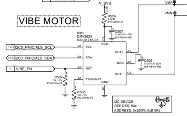
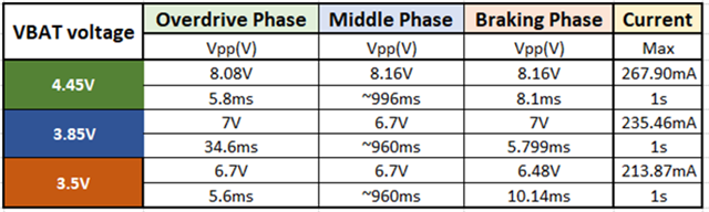
We used DRV2624 for vibrator driver. We used recommended RC filter from datasheet to do the measurement using scope. As test result, you can see the middle phase VPP is 8.16V when VBAT is 4.45V and VPP is 6.7V when VBAT is 3.5V. The result is over our estimated voltage. May you help check the setting for us? 

Regards,

Roy

  • HI Roy, 

    the peak overdrive voltage is set in Vp in the OD_CLAMP register field, and the 'middle phase' voltage is set in Vrms in the RATED_VOLTAGE field. What are the settings in this case?

    these programmed voltages may not be exact, so there may be a variation in the mV range.

    When you say the value is over the estimate, what was the estimate?

    Regards,
    Arthur

  • Hi Arthur,

    Sorry that I forgot to attach setting for you.

    rated voltage 5.56Vpp>2.0Vrms

    overdrive 7.0Vpp>3.5Vpk

    Our LRA frequency is 240Hz

    Now our Reg:1F, Reg:20 setting are showing as below

        0x4E, /* Reg: 1F, rated_voltage  (closed loop), see page 23 of datasheet, 2.0 Vrms */

        0xA5, /* Reg: 20, overdrive_clamp (open_loop), see page 23 of datasheet  3.5 Vpk */

    Detailed setting :

        0x4E, /* Reg: 1F, rated_voltage  (closed loop), see page 23 of datasheet, 2.0 Vrms */

        0xA5, /* Reg: 20, overdrive_clamp (open_loop), see page 23 of datasheet  3.5 Vpk */

        0x00, /* Reg: 2E, ol_period_msb, see below */

        0xA9, /* Reg: 2F, ol_period_lsb, OL_LRA_PERIOD[9:0] × 24.615 μs. 240Hz*/

        0x00, /* Reg: 2C, ol configuration (default), */

        0x40, /* Reg: 07, mode_settings, no LRA period average, pulse-triggered */

        0x88, /* Reg: 08, control_1, LRA mode, auto-brake before standby mode */

        0x00, /* Reg: 0D, control_2 (default)    0x10, /* Reg: 27, drive_time, (1/240Hz)/2==2.1ms */

        0x16, /* Reg: 21, AcalComp */

        0x90, /* Reg: 22, AcalBemf */

        0x37, /* Reg: 23, loopback_ctrl, brake factor 4x, slow loop gain, B-EMF 30x */

        1000  /* auto_cal_time 1000mS  */


    Motor information : 

    rated voltage 5.56Vpp>2.0Vrms

    overdrive 7.0Vpp>3.5Vpk

    240Hz

     And then the middle phase VPP measurement is 6.7V-8.16V. OD phase Vpp is 6.7V-8.08V.

    What is the output Vpp range in different VDD voltage?

    Roy

  • Hi Arthur is out of office and will respond as soon as possible, thank you for your patience!

  • Hi Roy, 

    are you measuring with a first order Lowpass filter? I think that the measurement of Vpp may be misleading. since the ouput is Class-D the outputs will always be switching between Gnd and Vdd at ~20kHz. So a first order LPF may not be filtering all of the high frequency content. this will affect the Vpp measurement because it will be switching to a higher votlage when Vdd is increased

    This device has a feature which monitors the supply voltage to account for battery discharge over time. As the voltage drops the output duty cycle will increase to maintain the same RMS level. this is mentioned in section 8.3.7 of the datasheet

    I just tested this with a setting of 1.5Vrms rated votlage. for 3.5V I see 1.4Vrms and for 5V I see 1.41Vrms on the output. So the feature is functioning as intended. 

    and regarding the 6.48 V braking in the 3.5V case. 7Vpp wont be attainable for 3.5V Vdd because the output FETs will have some Voltage drop due to RDSon.

     Regards,
    Arthur

  • Hi Arthur,

    Please see comments below.

    Did you measure with a first order Lowpass filter? I think that the measurement of Vpp may be misleading. since the output is Class-D the outputs will always be switching between Gnd and Vdd at ~20kHz. So a first order LPF may not be filtering all of the high frequency content. this will affect the Vpp measurement because it will be switching to a higher voltage when Vdd is increased.

    [GRMN] I measure the waveform with the 1st order LPF which is mentioned in 7.1 of the datasheet as image below, if this method can’t get accurate result, could you let us know how should we measure the waveform and get the correct result?


    This device has a feature which monitors the supply voltage to account for battery discharge over time. As the voltage drops the output duty cycle will increase to maintain the same RMS level. this is mentioned in section 8.3.7 of the datasheet.


    Your side just tested this with a setting of 1.5Vrms rated voltage. for 3.5V I see 1.4Vrms and for 5V I see 1.41Vrms on the output. So the feature is functioning as intended. And regarding the 6.48 V braking in the 3.5V case. 7Vpp won’t be attainable for 3.5V Vdd because the output FETs will have some Voltage drop due to RDSon.

    [GRMN] Could you help let us know if we want to get the result as below, what setting should we set in the registers

    rated voltage 5.56Vpp>2.0Vrms

    overdrive 7.0Vpp>3.5Vpk

    240Hz


    Besides, could you follow our setting and help check what result will be with this setting?

    Our setting

        0x4E, /* Reg: 1F, rated_voltage  (closed loop), see page 23 of datasheet, 2.0 Vrms */

        0xA5, /* Reg: 20, overdrive_clamp (open_loop), see page 23 of datasheet  3.5 Vpk */

        0x00, /* Reg: 2E, ol_period_msb, see below */

        0xA9, /* Reg: 2F, ol_period_lsb, OL_LRA_PERIOD[9:0] × 24.615 μs. 240Hz*/

        0x00, /* Reg: 2C, ol configuration (default), */

        0x40, /* Reg: 07, mode_settings, no LRA period average, pulse-triggered */

        0x88, /* Reg: 08, control_1, LRA mode, auto-brake before standby mode */

        0x00, /* Reg: 0D, control_2 (default) */????????????????????????????????????????????

        0x10, /* Reg: 27, drive_time, (1/240Hz)/2==2.1ms */

        0x16, /* Reg: 21, AcalComp */

        0x90, /* Reg: 22, AcalBemf */

        0x37, /* Reg: 23, loopback_ctrl, brake factor 4x, slow loop gain, B-EMF 30x */

        1000  /* auto_cal_time 1000mS  */


    Regards,

    Roy

  • Hi,

    Are TI expert is out of office today for US holiday, please be patient as responses are delayed

  • Hi Roy, I see you are setting many open-loop (OL) registers. Are you driving in closed loop or open loop?

    If you're driving in closed loop, then are you running auto-calibration first? (this sets 0x20-0x22 registers)

  • Hi Kelly,

    Thanks for the notes.

    We were driving in close loop and after the calibration:

    • The overdriving Vp is around 4.2 V while we expect it’s 3.5Vp.

    0x4E, /* Reg: 1F, rated_voltage  (closed loop), see page 23 of datasheet, 2.0 Vrms */

    • The middle phase Vp is around 4.0 V while we expect it’s 2.0Vrm(5.66Vpp, 2.8Vp)

    0xA5, /* Reg: 20, overdrive_clamp (open_loop), see page 23 of datasheet  3.5 Vpk */


    The overall output voltage is still not as expected.


    For the calibration, you said that it will set register 0x20-0x22, but when I read the document, this should be 0x21-0x23. Is this correct?

    And here are the calibration result for 0x21-0x23

    0x21

    0xc

    0x22

    0x91

    The last 2 bits of 0x23(BEMF_GAIN[1:0])

    0x2

    Any comments on these calibration results?

    Roy

  • Hi Roy, yes, my mistake above, calibration sets registers 0x21-0x23. There is no way to give feedback on the returned calibration. These settings are based on the actuator. 

    You are listing a lot of voltage values above and in previous messages.. It is not clear if you are getting too high of a voltage or too low of a voltage or a combination of these across VDD.. Can you please summarize your issue with clear oscilloscope screen shots of the output signal? (or put it in a PPT, this is too confusing to follow). Feel free to debug this over email - I think it would be much easier..

    For the register settings, you can either use the equations in the datasheet, section 8.6.2, or use Haptic Control Console (recommended). Remember you must factor in additional settings when setting the rated voltage. Based on 240Hz LRA, your settings look correct. 

  • Hi Kelly,

    Customer summarized the result in below attachment.

    Luna Vibe test.pptx

    Roy

  • Hi Roy, 

    thank you for this. from the measurements they are measuring the Vp and then I assume the customer is calculating the Vrms by taking the Vp/1.41. Correct? this method is not going to be accurate because the outputs still contain some switching, and there is blanking time between the positive and negative outputs to measure the Back EMF.

    Can the Customer take these measurements on the oscilloscope by taking the RMS measurement? This will be more accurate and I expect the result will be much closer to the programmed value.

    Regards,
    Arthur

  • Hi Arthur,

    Luna Vibe issue.xlsx

    As attachment, we use datasheet to calculate the estimated Vpp and we also measured it from oscilloscope.

    In addition, we also used oscilloscope VRMS calculation. Please double check whether we need do any modification in our register setting. Thank you.

    Roy

  • Hi Roy,

    I think that these measurements do not cause any concern. the output waveform of DRV2624 is a switching square waveform with deadtime between cycles, so it will be tricky to measure the waveform and make it match exactly to the programmed values. I mean that the measurement as taken on the scope will greatly depend on how the output is filtered. I talked with Kelly about this and the method that was used to validate the RATED_VOTLAGE and OD_CLAMP values when this part was made is complicated, and may require a specific oscilloscope to measure. 

    What is it exactly that the customer needs? they want to verify that the programmed value is being driven to the LRA accurately?

    Previously I have shown that the DRV2624 will adjust the Class-D duty cycle to compensate for drop in battery voltage, and DRV2624/25 have shipped millions of units over the past 8 years and issues of DRV2624/25 inaccurately driving LRAs and burning LRAs is not a common issue. 

    Regards,

    Arthur 

  • Hi Roy,

    I received your email we can take this offline. I will close the thread.

    Regards,
    Arthur