A related question is a question created from another question. When the related question is created, it will be automatically linked to the original question.
If you have a related question, please click the "Ask a related question" button in the top right corner. The newly created question will be automatically linked to this question.
Part Number: DRV8323R Other Parts Discussed in Thread: DRV8323,
A custom motor driver based on BOOSTXL-DRV8323RH design fails to run the motor and ends up frying itself and the mosfets. The circuit is designed based on TI designs and recommendations for the same.
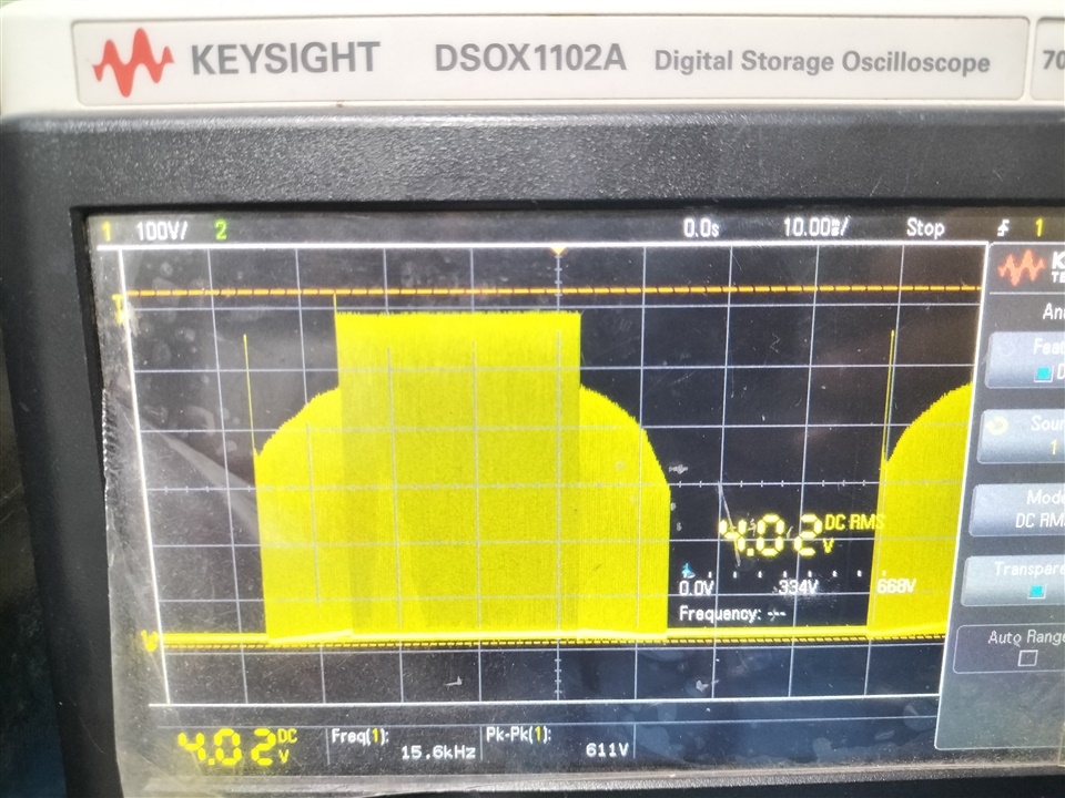
I finally got the motor working in a controlled manner. I am still using the lowest IDRIVE setting ( IDRIVE shorted to ground). The motor spins but makes a rough noise. I am using a 16 kHz PWM. Here is the trace for one of the Mosfets gate. It should be trapezoidal, but can't figure out the reason for the following shape.
Here is the trace for one of the Mosfets gate. It should be trapezoidal, but can't figure out the reason for the following shape.
Is it GHx, GLx, or Watergate? Without know the voltage/division -- not obvious to me -- I don't know what I am looking at. Please don't let us guessing as no help to you.
Here is the trace for one of the Mosfets gate. It should be trapezoidal, but can't figure out the reason for the following shape.
If the waveform is GHx, then it should be in 16khz PWM shape, not trapezoidal. Why do you expect it to be trapezoidal (or sinusoidal in an idea case)? You have to do a low pass filter in order to see the trapezoidal shape of the 6-step Hall commutation.
I have a BOOSTXL-DRV8323RH EVM Board by TI. I have configured it in 1xPWM mode. I observe the motor performance on the EVM board and also the waveforms at various nodes to that of my custom board. The voltages posted in the earlier post were found similar to that of EVM board. Also I observed a neat trapezoidal waveform at GHx as opposed to by custom board. I think if I resolve this issue, then the motor performance may improve.
Based on your initial waveform that you shared, could it be possible that the hall sensors and motor phase wires are misaligned? You seem to be experiencing something similar to other users who found that their hall sensors were misaligned and saw that correcting this fixed the issue.
Hello Alicia, I do agree with your point. Infact, I faced the same issue a couple of months ago while testing BOOSTXL EVM Board. I did get it resolved and got the board and motor working perfectly.
But this time I am sure that its not the issue. As I have mentioned before I regularly check the motor used with BOOSTXL Board to check validity of the motor and my connections too.
Also, as per your suggestion I'll go through the threads and FAQs as well.
GHx is 16khz pwm and should have the same peak voltage instead of a trapezoidal shape. What is the time T shown below?
The captured scope waveform missed many important parameters such as the voltage scale and time scale, and so I don't know if the pic shows many hundreds pwm cycles or something else. Again, there is no reason for the GHx to have different voltage level as shown.
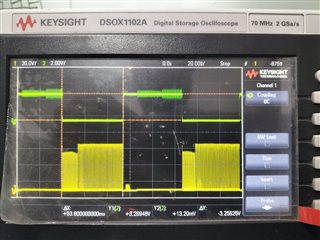
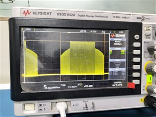
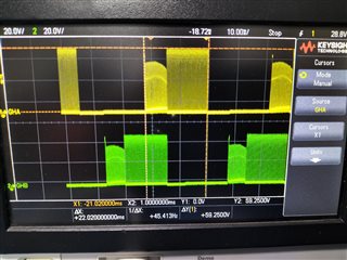
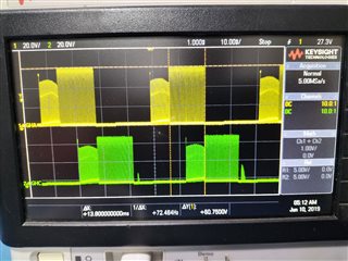
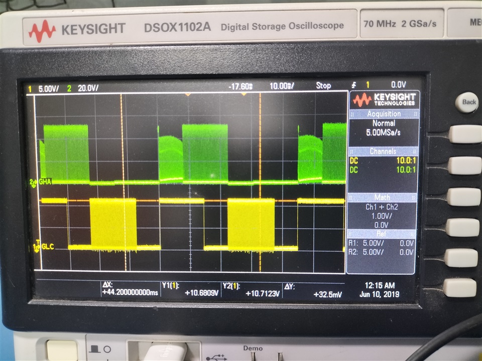
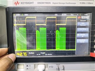
Hi Alicia, as per your suggestion here is the plot of HALL Sensor A (yellow) and SHA (green). The small bump at the beginning (right) goes to the end (left) if I change the direction of the motor. Also, I tried changing the bypass capacitors at the hall sensor input to 1 uF instead 1 nF, but no difference. This plot is for 1 uF setting.
Hall signal looks normal. SHx could be distorted due to motor BEMF, so why not capture GHx together with Hall signal, as it should have the same peak voltage every pwm cycle.
Hi Alicia, as per your suggestion here is the plot of HALL Sensor A (yellow) and SHA (green).
OK, now we get something.
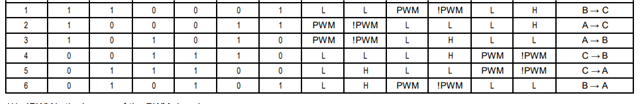
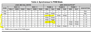
The GHA has 3 levels: 0v, HV1, and Hv2 where HV2 > HV1. Let me explain why we see two level HV1 and HV2 instead of just HV2. During 6-step Hall commutation, each phase goes through 3 states: 0v (with lower FET turned on), HV2 (when upper FET turned on) and floating at HV1 (when both FETs turned off), according to the table below. During Fets turned off, the voltage at SHA is driven by the other phase that being PWM via the motor coils.
So nothing is wrong with the waveform and you should not expect to see a trapezoidal waveform.
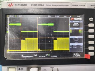
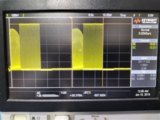
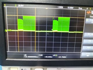
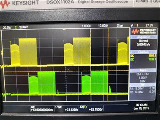
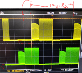
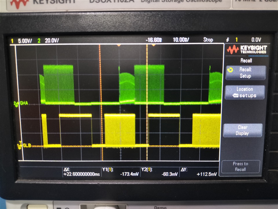
Hello Brian, Thanks for the detailed explanation. Let me show you my problem in more detail as well. Here are the two waveforms observed from BOOSTXL board and custom board. Both traces are SHA at same frequency (16 kHz) and same duty cycle (10 %).
Ill also upload the video for MOTOR running using both BOOSTXL and Custom Board. The motor starts and runs smoothly with no audible noise or any significant vibrations with BOOSTXL Board. Whereas, using Custom Driver the motor needs a kick-start and also makes an audible noise and vibrations while running.
I want to obtain the same performance with the custom board as observed on BOOSTXL board. Also, the MOSFETs keep frying at higher speeds i.e. with 50% duty cycle.
The Boostxl waveform conformed to the table below, but your customer waveform does not. I will point out where is the problem as I continue to edit this post because I couldn't add more pic to it for some reasons by the forum website.
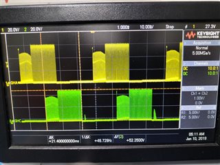
Each commutation cycle is about 8 divisions based on scope capture, and so there are 3 equal parts on the time scale: 2.7 div pwm, 2.7 div zero volt (low FET turned on), and 2x of 1.3div of floating voltage (both FETs are off). Let's look at phase A on the table below: hi-z, then 2x pwm = 2.7div, then hi-z, then 2.7 div of 0V. This logic is matched with the waveform above.
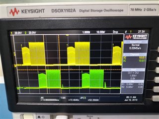
Now, let's look at the customer waveform: each commutation cycle is about 5 div, so the pwm = 1.8div and 1.8div of 0v. The floating is about 0.8div each. This issue is right after the pwm section, there is no floating FETs but instead the lower FET is ON. This caused the problem and the motor noise. You should look to see why the lower FET is turned on instead of off at step 4 of the 6 step table below.
Are you using 1x PWM mode or some other input mode?
The peak-peak voltage for hall Sensor is ~ 3.3 V as expected.
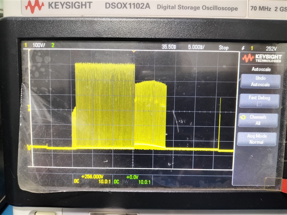
The peak-peak voltage for GHA is ~ 5-7 V .
The peak-peak of GHA of 5-7v is super low; you should double check as I don't believe it - with 51 on the FET Drain, there is no way the high FET can turn on with just 7v p-p. Also why I couldn't tell the v/div on your captured scope screen? Can you teach me how to read the signal voltage on the scope?
I expect the GHA signal to have the "float" level right after the PWM section, just like the "float" before the PWM.
Could you capture these signals on the same screen: GHA, GLB, GLC. This will help to explain why GHA has the weird shape.
Hello Brian, I apologise for the mistake in previous post. I actually have some difficulty in measuring voltages on my CRO. I was sure that the hall sensor Signal must jump from 0V - 3.3V. I tried to measure the GHx peak to peak using the same reference level. But I think I must have made some error while calculating the voltages. Since the motor is running there is no way that the GHx pin has anything less than VM. Let me get back to you in a couple of hours. Will figure out the CRO issue or atleast get the same data using DMM. Also, I have a 2 channel CRO. Will try to get all three traces in pairs of 2 each.
Also, the pwm is generated using and extyernal square wave generator at 5V peak to peak voltage and the ground and PWM o/p pin connected to that of drivers ground and PWM pins.
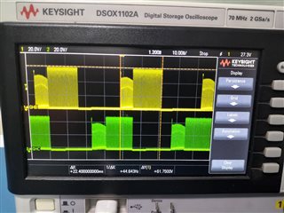
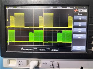
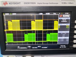
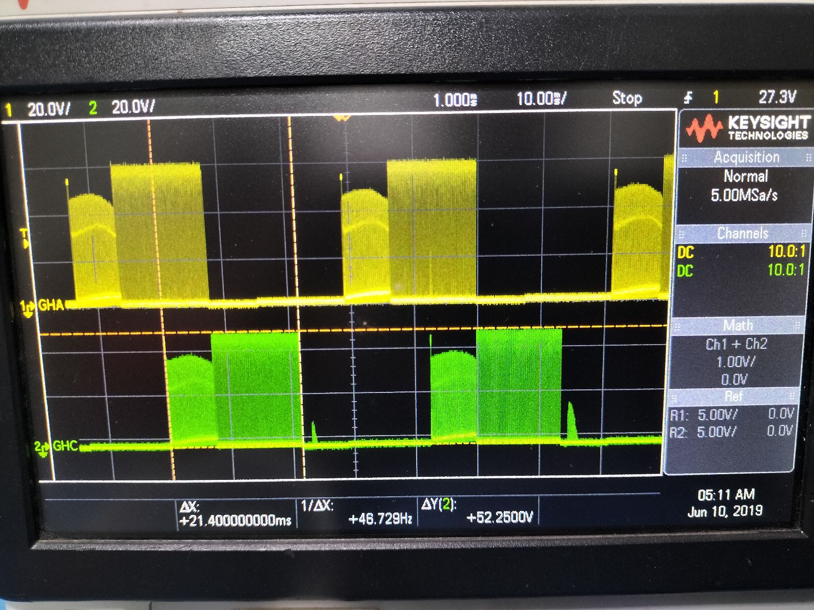
Hello Brian, here are the traces you asked for. VM = 51.4 V, PWM = 16 kHz, 10% dutycycle
Hi Aniket,
To make life easier for everyone: line up the waveform bottom 0v on the grid and the pwm cycle (the period of each cycle) start point on the grid. This practice helps to measure the voltage and time much easy than what you posted.
Hello Brian, here are the traces you asked for. VM = 51.4 V, PWM = 16 kHz, 10% dutycycle
Hi Aniket,
I asked for GHA and GLB, GLC. Not all GHx as you had captured. The GLb and GLc will help to explain why the GHA doesn't have the floating section after the pwm. Pay attention here: Gate Low B and Gate Low C, not GHB and GHC.
Why do I want to see GLB and GLC? if they turned on then the lower FETs are grounded which cause the missing "floating" section on GHA.
Also, what's wrong with your scope or probes: Some pic with waveform having 3 div p-p, and some with only 2 div p-p? Are these waveforms captured with the same supply to the FET drain of 52v?
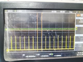
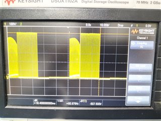
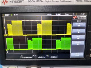
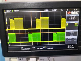
Could you post the scope waveform of SHA and SHC captured together on the same pic? Pic below shows the GHA and GHC, but I want to see signals at SHA and SHC (which are connected to the motor wires).
As I pointed out before, the Hall signal relative to the GHx signals are inverted. However looking at the all the gate signals, GHx and GLx, and they don't seem to cause the problem of missing "floating" section after the PWM section.
Hello Brian, I did check the hall sensors and everything is as described by the DRV8323 datasheet.
Really? Pic below shows GHA and GLA are pwm during Hall A is low, and you are saying it is correct based on the 8323 datasheet?
Look at the table below and tell us at what step in the table that GHA with pwm when Hall A is low. I had pointed to this problem 7 days ago. There are only 6 steps so you have 1/6 probability of point to the right step, but I am sure you can't find the correct one.
Hello Brian, this is what I meant when I said, hall sensors are connected according to DRV datasheet. INLA = HALL_A, INHB = HALL_B, INLB = HALL_C. As I have mentioned earlier I do check the same motor in BOOSTXL kit using the same configurations as with Custom driver. I did compare the waveforms from both the drivers and I do agree with the inconsistencies. Hence, I am posting this in the forum. Hope to get this issue resolved with your help. I have provided the data you have asked for. I would appreciate a decent tone and less sarcasm in your replies. I understand and share the same frustration. As per your previous suggestion of HALL sensors out of sync, have checked the PCB for the same as well. I have the configuration as INLA = HALL_A, INHB = HALL_B, INLB = HALL_C. I have tested the other combinations and that didn't help.


 Hi Alicia, as per your suggestion here is the plot of HALL Sensor A (yellow) and SHA (green). The small bump at the