Dear Team,
We have planned to use DRV8962 IC in our project need to get clarify about the current flow through the IPROP1 and OUT1 load pin ,
Here By I attached the image for your reference.
Kindly help us on this .

This thread has been locked.
If you have a related question, please click the "Ask a related question" button in the top right corner. The newly created question will be automatically linked to this question.
Dear Team,
We have planned to use DRV8962 IC in our project need to get clarify about the current flow through the IPROP1 and OUT1 load pin ,
Here By I attached the image for your reference.
Kindly help us on this .

Hey Pooja,
Thank you for your question.
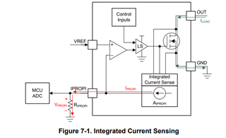
The IPROPI pins source a small current that is proportional to the current in the high-side MOSFETs. The sense accuracy of the IPROPI output is ± 4% for 40% to 100% of rated current. External power sense resistors can also be connected if higher accuracy sensing is required.
I suggest reading section 7.5.1 of the DS for more information.
https://www.ti.com/lit/ds/symlink/drv8962.pdf

Best,
Akshay
Dear Akshay,
Thanks for the replay,
We are using Resistive load at Output1 side ,IN1 is controlled by SOM (PWM 10KHz)3.3V
EN1 is given by SOM (3.3V)
Output of DRV8962 is PWM 24V
Our plan is to measure the current flow at Internal or external regulation pin and set the PWM according to the flow of current in the Output1 side.
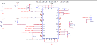
Here By I attached schematics of DRV8962 IC ,
Requesting you to review on this and let me know your feedback.
1) There is 2 Type of current regulation is DRV8962 IC
1 a. Internal current regulation
1 b. External current regulation.
If I use Internal current regulation ,is that possible to measure IRMS current or Using external current regulation
Please confirm me ,
Which type of current regulation suits to our application.

Thanks,
Pooja Ak
Hey Pooja,
Either the internal current regulation or the external current regulation can work to regulate your current. The choice depends on how much accuracy you need.
Section 7.5.3 of the Datasheet contains information that might be relevant to your decision.
Please find the attached schematic pdf with some feedback.
Best,
Akshay
Hi Akshya ,
Thanks for the review.
I will update.
Here I attached the image and link which I received input from your Team,
As your team conveyed to me, you can't use Internal current regulation for controlling the current .
Iam in confusion state now 
Is that possible to sense the IRMS current using IPROPI1 pin.
Doubt: I set ITRIP value as 200mA and connected the resistive load(Heater) at output1 side , load consume maximum of 160mA with condition of 100% Duty Cycle
Let's imagine I reduced the IN1 (PWM) to 10% ,By this case IRMS value is 0.0476A is that same current will flow in OUTPUT1 side or maximum of 160mA will flow in outPUT1 side?
Requesting you to helps us on this.
DRV8962: Fixed Frequency - Motor drivers forum - Motor drivers - TI E2E support forums

Thanks,
Pooja Ak
Hey Pooja,
I believe Murugavel was concerned that with a resistive load the current threshold will be reached very quickly.
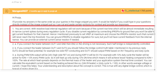
"Yes if you want to completely disable regulation and do not want any IPROPI feedback to the MCU you should connect it to ground. In the schematic you sent over the previous message it was floating. If you do need an analog equivalent voltage of the output current an RIPROPIx is needed on IPROPIx and sized such that although regulation is enabled it will never reach the Itrip value thereby never in the zone for regulation. And if IROPI1 was not set, the IC will not be damaged specifically with no load connected or no short circuit in the output. Even in this case internal OCP protection would kick in and protect the IC." - Murugavel
So in this manner you get an equivalent voltage of the current in the HS mosfet but never reach the trip voltage for regulation.
You are not measuring the IRMS current using IPROPI, but you can see a proportional current as seen across the HS fet.
Could you explain how you got 0.0476A?
Best,
Akshay
Hi Akshay,
Vrms= Amplitude Square root of (Ton/T) F=10KHz ,T=0.0001,
10% of Ton is 0.00001
20% of Ton is 0.00002
30% of Ton is 0.00003
100% of Ton is 0.0001
Amplitude = 24V
Vrms for 10%=24 square root of (0.00001/0.0001)
Vrms for 10%= 7.589V
V=I X R
Vrms=I HS X R( Load)
IHS=Vrms/R (Load)
IHS =7.58/159(Load)
IHS= 0.0476A
For 10 % of PWM current will flow 0.0476 A at OUT1 side
If I increase the PWM to 20% case IRMS current is 0.076A ,
My question is now
If I applied 100% of Duty cycle (PWM) by this case 160mA will flow at OUT1 side correct right ,In the same way If I Reduced PWM to 10% whether Current will change at Output1 side or Not
Kindly clear this point.
Hey Pooja,
With a resisitive load the current you measure at the output will look more like a square wave. So with 100% Duty cycle you will see 160mA and with 10% duty cycle you will see 0.1*160mA = 16mA.RMS current is more relevant for since waves.
Hope this helps.
Best,
Akshay