This thread has been locked.

If you have a related question, please click the "Ask a related question" button in the top right corner. The newly created question will be automatically linked to this question.

DRV8889-Q1: smart tune ripple control

Part Number: DRV8889-Q1

Hi team

Do you have more detailed information regarding the smart tune ripple control mode of DRV8889-Q1? Customer needs to better understand how our device control the PWM chopping and the ripple to analyze the EMC behavior


For example, in below picture in datasheet, for the on time regulation, point1 seems to be reaching the Itrip, which point 2 seems to be hitting the tblank time. How the device calculate the on-time?

And for the off-time, it seems the device regulate by hitting the Ivalley.

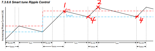
And in below picture, how device regulate the stage2 and stage3?

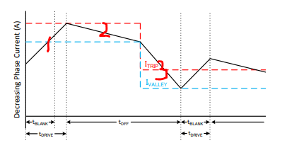
And could you help confirm with us how device adjust the Itrip and Ivalley?

Thank you

Scarlett

  • Hi Scarlett,

    Smart Tune Ripple Control uses slow decay almost all of the time. When the current regulation exceeds 10% of the Itrip value STRC will use fast decay. It is possible the fast decay stage may keep regulating at the Itrip 10% level in full-step mode when the back EMF of the motor is high usually at high step rates. See this post; https://e2e.ti.com/support/motor-drivers-group/motor-drivers/f/motor-drivers-forum/1247121/drv8424-unstable-period-of-current-regulation-in-full-step.

    For the DRV8889-Q1, ΔI = ITRIP- IVALLEY = 12mA + (1% of ITRIP). This is internally fixed value for STRC. In the figures you showed tDRIVE is same as tON. tON is determined by the supply voltage VM and motor characteristics L/R time constant. This can be calculated using this relationship formula, ITRIP = ((VM-BEMF)/R) x (1 - e-tON x (R/L) ), BEMF is the back EMF voltage which is = 0 at stand still, R is the DCR of the stepper winding and L is the inductance of the winding. Based on this formula you can see tON will be faster if the supply voltage is higher. 

    Now referring to the diagrams you have shown, the current increases in the winding until it reaches ITRIP with duration tON. As soon as it reaches ITRIP (#1) the bridge is turned off and the current decays with slow decay until it reaches IVALLEY (#4). Then the bridge is turned ON again and this cycle will be repeated. Usually tON > tBLANKING. However with higher VM supply voltages it is possible current through the winding can exceed ITRIP within the blanking time (#2). In this case as soon as the blanking time is elapsed the bridge will be turned off. TOFF is determined by the time it takes for the winding current to reach IVALLEY. When the stepper is spinning, its BEMF will be a sine wave whose frequency and amplitude are a function of the motor speed. At faster speeds the BEMF amplitude and frequency will be higher. TOFF will be variable according to this because BEMF is variable. This application note discusses TOFF vs. BEMF,   https://www.ti.com/lit/an/slvaei3/slvaei3.pdf. #3 is an example where current is decreasing, new ITRIP < previous ITRIP. This happens in microstepping while the current is in Q2 quadrant of the sine wave which results in decreasing phase current.


    All these are automatically carried out by the driver's built in index and smart tune ripple control algorithm based decay mode.

    Regards, Murugavel