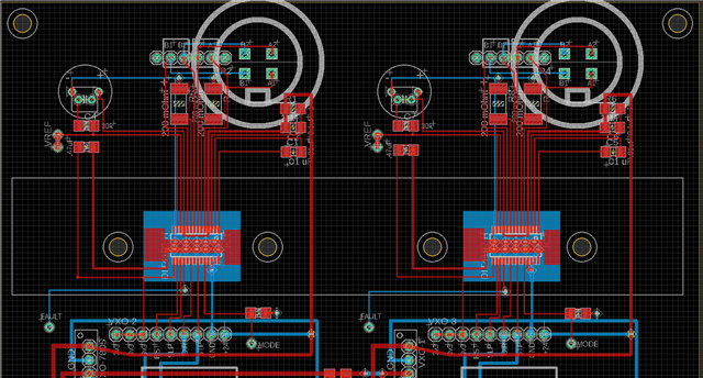
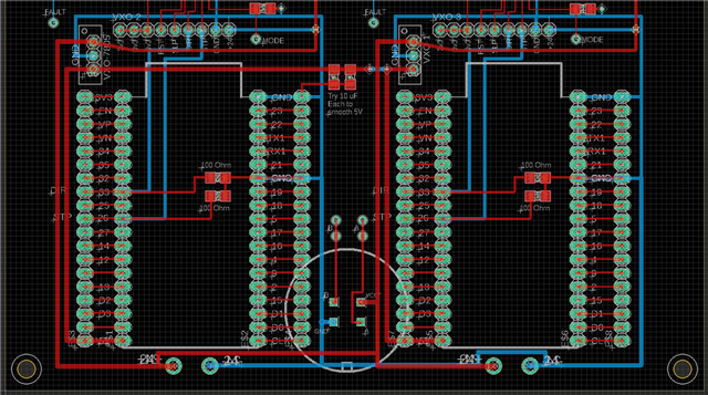
The problem is how one of two motors (one stepper driver on each) eventually stops. The fault pin goes down to zero volts.
So I am wondering why the fault pin is logic low to begin with. It is on a custom PCB (not a carrier or dev board).
This thread has been locked.
If you have a related question, please click the "Ask a related question" button in the top right corner. The newly created question will be automatically linked to this question.
The problem is how one of two motors (one stepper driver on each) eventually stops. The fault pin goes down to zero volts.
So I am wondering why the fault pin is logic low to begin with. It is on a custom PCB (not a carrier or dev board).


Hi Adam,
Does the fault occur right away or does the motor run for a while and then the nFault LED goes off. Is this behavior repeatable on the faulty device or does it happen at random? Can you send me the schematic for the layout you have shown above. If it sometime of thermal shutdown event, I can refer you to this application note that gives you best practices for a board layout for a motor driver. Can you also try to capture the current at the output and the voltage on the input when nFault goes low.
Best Practices for Board Layout of Motor Drivers (Rev. B)
Best regards,
Keerthi Kumanan
When the nFault goes to zero, it stops completely. There is no LED. It's just what a measure with a DMM.
The first PCB I assembled, it happens after a long time (51 minutes). For there, I assembled four more. Those other PCBs, the nFault gets triggered on one of the drivers (not always the same one) after about a minute. I swapped stepper motors and confirmed it is the drivers and not the motors. The motors have a rating of 2.8 A/phase.
There is no schematic for the layout just the footprint.
capture the current at the output and the voltage on the input when nFault goes low
Measure the current through where? The power supply?
Hey Adam,
I recommend downloading the Gerber files and opening it up in whatever PCB design software you have used to get an idea of what a good design looks like. I attached the schematic for the EVM below. Usually, you make the schematic and then go to layout.
What software are you using?
Best,
Keerthi Kumanan
I have encouraged the engineer senior to me to create schematics (the one who created the footprint). Sometimes they do, sometimes they do not.
We're using EAGLE.
Hi Adam,
Once they do make the schematics, you can send them, and I can review them for you. Then you can work on a better layout, and I can do a layout review as well.
Best,
Keerthi
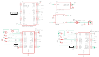
This is just an experimental PCB. It's not going to be a product or anything. For a different version I got ground layers to be added. But it's not worth redesigning the whole board a third time since this is not going in the product. Here is a related schematic:
Hey Adam,
Does your device get hot when the motor stops? With your layout I'm wondering if there isn't sufficient cooling for the device. Try touching the top of the DRV device after a minute or two of driving the load.
nFAULT goes LOW when a fault condition occurs, such as overtemperature or overcurrent.

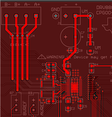
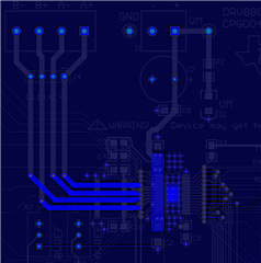
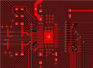
See below for some more pics of improved layout for your future designs, for the EVM we used a 4-layer board but a 2-layer PCB could also work.
All 4 layers (Top/GND/GND/Bottom) - note the placement of all the capacitors near the device.
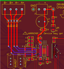
Just top - note notes of GND plane.
Bottom layer - nice thick traces for the output current
Zoomed in on the chip:
Thank you for the layout tips and diagrams, but I had no control over that on this one. One driver circuit worked previously, and another person simply copy/pasted the board design for two on one board.
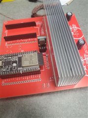
There is a very large heat sink over both driver ICs. I even had a fan on it. A screw drilled into the heat sink measured a cool 30 C. It did not go over 31 C, even when one of the two stepper motors stopped.
Again, the stepper motor is rated at 2.8 A/phase. The drivers are, best case, rated up to 2.2 A/coil. So I believe that is why one motor is stopping (overcurrent). Although, that does not really explain the logic low 0.25 V on the fault pin to start with. That is what I'm trying to figure out.
Hey Adam,
Try feeling the underside of the PCB when driving the motor just to make sure. Since this device has the PowerPad on the bottom of the device, the majority of its heat will be dissipated through that pad into the PCB and only some of the heat will go through the plastic device package and into the heatsink. It's possible the device is warming up faster than the heatsink can remove heat and causing an overtemperature trip internal to the device. I agree with you though that overtemperature is unlikely in this case.
As for the 0.25V issue, can you confirm the ESP32 pin is set as an INPUT, and has the internal pull-up/down resistors disabled? The 0.25V could be due to the pin having it's internal pull-up resistor enabled on the pin reading the nFAULT voltage.
Also try changing the GND connection location when you're measuring that 0.25V - the GND connections are so flimsy on the board I'm wondering if it's just a voltage difference in GND itself.
Regards,
Jacob