I cannot move a motor with my MCF8316AEVM evaluation kit.
Essentially, what happens is I will setup the device as per the instructions both from the user guide and the web GUI. And when I try to move the motor by adjusting the position of the motor control potentiometer the motor moves for half a second and stops. This causes the nFault LED to turn on and it also yields an MPET IPD Fault (as reported by the GUI).
Steps taken to resolve the issue:
- Using manually measured MPET values into the default (EEPROM) registers for manually calculated MPET motor values.
- Manually checking the motor phase wires are indeed connected
- Increasing the MPET IPD current threshold (I tried this a few times, each time iincreasing it to the enxt available setting until I set it to the max current threshold)
- Entering the manually calculated MPET values (specifically motor inductance and resistance) in the ‘fault handling’ section for the MPET IDP Fault.
- Using calculated phase resistance (this calculated in the GUI by entering the resistance measured when probing the resistance between any two of the three motor phases)
- Entering the default values (as per the device datasheet) into thier respective EEPROM registers
- Increased the MPET_IPD_CURRENT_LIMIT to its max value of 2A
- Increased the MPET_OPEN_LOOP_CURRENT_REF to its max value of 8A
- Probing the phase control outputs (from the evaluation kit), both without a motor connected and with a motor connected. For both tests, the module is completely reset (as outlined ‘blank-slate’ above) and the outputs for each motor control phase were probed.
What we found is each phase would output a PWM signal. For the test without a connected motor, each phase was at a higher voltage than the other. With the test with a motor connected, each phase outputted a PWM signal with each being the same voltage. - Loaded the devices registers with thier default values (as per the user guide)
- Increased the IPD current limit
- Set the default startup behaviour to IDP
These steps all still have the same result. The motor (if it is connected) moves briefly, for less than a second and then the nfault LED powers on along with the GUI reporting an “MPET_IPD_FAULT”.
Additionally, each time a test is run what I observed was that my power supply (supplying motor power to the board via VBAT and PGND) would draw 26mA while the motor control pot is set to its zero position and once it is set to a non-zero position it would draw 33mA for a brief second and then sit at 30mA. There was no observed indication that the motor was attempting to draw any current at all. All these tests were conducted with 12v supplied to motor power, and have been conducted with multiple brushless motors.
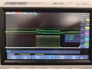
Additionally, I configured the VSOX pin to output a signal indicative of the current draw for the A-phase channel, to better understand what may be causing this issue (as MPET IPD Fault indicates either the device has detected no motor to be plugged in or that the motor is attempting to draw a greater current than it is allowed to do so).
What I found was the VSOX pin outpoutted a waveform which was around 50mV, which I assume is indicative of a low measured current for the A-phase channel. This would align with what I have been observing in that the motor does not move much for very long. However this is confusing given I observed this after setting the HW_LOCK_LIMIT to its max value of 8A, and the motor stops if VSOX > HW_LOCK_LIMIT.
I have attached the reading from my oscilliscope for this below, along with an image of the observed waveforms of th a, b and c phase channels of the device when runnign this tests with not motor connected.
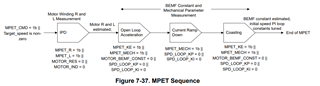
Finally, I have also tried getting the device to run through the MPET sequence to measure the motor parameters but it fails.
What I would like to know is how can I get this module to spin a motor, what is causing the device to think the motor is either not connected or drawing too much current (Because I am quite confident niether of which is happening) and if we can get the MPET working?
I am very much at my wits end with this module because it feels as though I have done almost everything I possibly can to fix this to no avail!
Looking forward to hearing some answers on this - thanks in advance.
This is the measured waveform of the a, b and c phase channels of the device when running these tests with no motor connected, all channels are set to the same voltage level on the scope in this reading
This is the measured waveform of the a, b and c phase channels of the device as well as the VSOX (in green) when runnign these tests with a motor connected.
The VSOX waveform has been shifted up to make it more visible. Additionally, the phase channels have all been set to the same position and are the same size.