This thread has been locked.

If you have a related question, please click the "Ask a related question" button in the top right corner. The newly created question will be automatically linked to this question.

DRV8889-Q1: Issue with write and read the SPI register in DRV8889

Part Number: DRV8889-Q1

Hello Team!

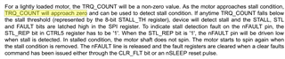
We are facing SPI communication issue with DRV8889 while setting up the stall detection register.

Is it always required to change the state of nSleep pin of the stepper driver to read/write the SPI register.

I have referred the sensorless stall detection application note as well and set all the parameters as required, still the registers are not getting properly updated.

Hope you can provide some solution over this.

Regards,

Agnideep.

  • Hello,

    It is not required to cycle nSLEEP for SPI communication.  Something is not correct with the communication itself.  Do you have an EVM or your own board?  Please share scope capture of all SPI signals in high resolution so we can check timing.

    Regards,

    Ryan

  • Thank you for the insight. I have checked with the timing of all SPI signal it's as per the requirement, now I am able to read and write the SPI signal. 

    Could you please confirm me the TRQ_CNT register updates continuously as the per the coil current of the motor in stall condition

  • Hey Agnideep,

    Yes, it will be updated continuously. However in a stall condition TRQ_COUNT will be 0 or close to 0 (below stall threshold) Check out  7.3.11.5 Stall Detection in the datasheet for a full description of TRQ_CNT.

    You might also want to check out Sensorless Stall Detection With the DRV8889-Q1

    Regards,

    Jacob

  • Hello Jacob!

    I have checked with the application report, which helped me to start with the implementation. But when I run my motor I get the TRQ_COUNT. I will describe my implementation in detail.
    1. I have set my stepper into micro-stepping mode which is 1/4 so I configured CTRL 3 register to 0x74
    2. Setting of smart ripple register is done, so the configuration of CTRL 2 register is 0x0f

    3. CTRL 5 register is been configured to 0x38 (Set to the stall learning mode) also I have done without Stall learning mode at that time I have configured it to 0x18. So when I have not set the self learning mode at that time I have set STALL_TH (register 0x08) to 0xA0 (This condition haven't shown up any fault or my stall bit haven't set to 1)

    4. After configuring this register, I have written the code to rotate the stepper motor.

    5. Now after the rotation I read the TRQ_CNT (register 0x09) the value came up with 0xB0 in steady state

    6. After this again I ran the stepper motor and stalled it with some external force, in this condition the TRQ_CNT register should update with different value but it came up with the same value on i.e. 0xB0.

    So, in above steps which I followed is correct or do I have change some other approach to get the continuously TRQ_CNT register update.

    Also, an example code will help me to get the solution.

    Regards,

    Agnideep.

  • Hi,

    Thank you for your question. Please expect a few days delay because Jacob is OOO.

    regards

    Shinya Morita

  • Hi Agnideep,

    If you are looking at the register values in the GUI either with the count values or in the register page register 0x09 you will not get the real-time value because the update rate is once per second or longer. To visualize the count updates faster you can use the analog output provided on the EVM on the test point shown by the red arrow in the below image. 3.3V on this TP is equal to a torque count of 255 and 0V is 0. Ignore this suggestion if you were reading the torque count register fast enough with the MCU on your PCB. 

    Based on the information you shared it appears the torque count is not changing when the motor was stalled vs. spinning normally. Can you provide more information about the stepper motor used? Coil DC resistance and inductance of each winding if datasheet is available please share, supply voltage for VM, current setting I full-scale, and STEP input frequency. 

    Regards, Murugavel

  • Hello  Murugavel!

    Thank you for your insights on this. We don't have the EVM, we are implementing torque count in our application based PCB.

    Below is the details which you required regarding the motor and PPS set for our application.

    1. Coil DC resistance : 58 ohm

    2. Coil DC inductance : 51.4 mH

    3. Supply voltage VM : 12V

    4. Current setting I : 100% (full scale)

    5. STEP input : 3334us (300 PPS)

    I have attached the electrical specification for the ready reference. Kindy refer the D2B bipolar column

    Can you please tell us more about the timing required for the torque count to update in register.

    Or how we can check the same in our own PCB application. 

    Regards,

    Agnideep.

  • Hi Agnideep,

    Thanks for the additional details about your application. Based on our bench experiments with various steppers we found steppers with DCR > 10 Ω do not generate enough back EMF amplitude resulting in poor SNR for the stall detection block to function reliably. Lower step rates have compounded effect on this situation. Unfortunately D2B motor with high DCR and L is not suitable for use with DRV8889-Q1 for stall detection. This is why you were unable to detect a stall condition with this stepper. The D3B is best suitable followed by potential usability with D1B on the spec sheet you shared. 

    By read rate I meant how often you sampled the TRQ_CNT register. Especially if you are comparing with a threshold externally using microcontroller you may have to have at least one sample per electrical half-cycle of the current waveform. For internal stall detection this is not relevant. You need to wait for the nFAULT pin status to change.

    Regards, Murugavel