This thread has been locked.

If you have a related question, please click the "Ask a related question" button in the top right corner. The newly created question will be automatically linked to this question.

DRV8703-Q1: .

Part Number: DRV8703-Q1

As you mentioned we had connected SP, SN pin to GND, so there is no voltage gap between them now

but we face below situation. 

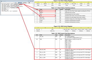
All VDS monitor function is disabled and SP-SN voltage difference is '0' but OCP flag is HIGH when we input 33[%] PWM duty cycle in IN2 pin

(MODE is '1', IN1 is HIGH, under 32[%] duty cycle is fine, PWM frequency is 80[khz])

Can you tell me any possibility about this problem?

  • Hey Pyeongkwon,

    Have you measured the current on the output to see if the OCP error is legitimate?  What load do you have on the output? 

    And does the same happen at lower kHz, like 20kHz? 

    Regards,

    Jacob

  • I use solenoid as a load but above situation happend even I set no load (open solenoid),

    and 20[khz] PWM output also set OCP bit.

    But, I find out that they(20[khz] and 80[khz]) set OCP bit if absolute PWM turn on time increase over 4[us]

    (It is almost 33[%] duty cycle in 80[khz] control, and almost 8[%] duty cycle in 20[khz])

    Does it can be kind of hint..? about this problem

  • Hey Pyeongkwon,

    When OCP bit changes, is the nFAULT pin LOW?  I think it might be a SPI communication issue.  

    With VDS Sensing disabled and the inputs shorted to GND, there should be no way for a VDS/OCP fault to occur, unless there is a voltage difference between the VDS pin GND and true GND

    Regards,

    Jacob