This thread has been locked.

If you have a related question, please click the "Ask a related question" button in the top right corner. The newly created question will be automatically linked to this question.

DRV8353F: DRV8353FH

Part Number: DRV8353F

Hi

We have designed a motor driver board for BLDC motor using DRV8353FH.

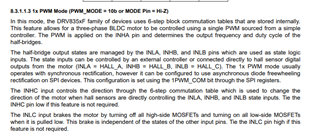
In this we have connected the HALL Sensor and the Motor U ,V , W connections and we have used 1X PWM mode.

After Giving the PWM frequency we could not able to run the motor. We have given the frequency of 25KHZ.

Expecting your favorable reply.

  • Hey Max,

    Thanks for the question.

    1) Have you ensured that the correct mode is being set in the device using the MODE pin and that THE APPROPRIATE INPUT SIGNALS ARE BEING SENT TO THE INHX and INLX?

    2) Have you checked the INX and GHX/SHX waveforms to see how the input output signals are being sent properly? You can check the gate to source voltage to see if the FETS are turning on.

    3) Are you monitoring the fault line to see if the driver is in a fault casing shutdown?

    4) Please check out the common questions section for more diagnostic help:

    https://e2e.ti.com/support/motor-drivers-group/motor-drivers/f/motor-drivers-forum/1176539/faq-quick-guide-to-debugging-common-issues-in-bldc-motor-drivers

    Best,

    Akshay

  • Hi

    Thanks for the Reply.

    We have connected the motor and all faults cleared.

    We are using 1X PWM mode in our design .

    We are giving PWM pulse on the INHA pin and connecting the hall sensor as recommended in datasheet.

    We are receiving the  signals(20KHZ frequency,50%duty cycle) at the inputs, But the motor does not rotate and sometimes the board gets heated.

    THE FET are getting the voltage when it is powered on. and no fault occurs.

    Kindly help us to proceed further.

  • Hey Max,

    Could you share your schematic with me?

    Best,
    Akshay

  • Hi

    1.What is your VM and Vdrain voltage?

    We have shorted the VDRAIN and VM pin  and we are giving a voltage of 20V

    2) The IDRIVE and VDS pin setting: The pull up is DVDD which is 5V typical.  

    We have connected the IDRIVE and VDS to 5V,Meanwhile it necessary to connect the Enable ,nfault to connect to 5V?.

    3) Is there load on the motor upon startup during your testing?'

    No we do not connect any load on the motor.

    4) Have you measured:

    a) VM, Vdrain, VCP to check correct/expected voltage?

    b)  Enable pin, INHx and GHx to SHx and SHx signals?

    Yeah we have measured the VM VDRAIN VCP it is as expected

    Enable Pin is connected to MCU and is pulled high.

    W.r.to schematics review we did not connect any Bulk cap on the VDRAIN pins.

    Also We have connected the Motor driver to MCU and we are using 1X PWM Mode.Hall sensor has been connected to INLA,INHB,INLB and we are giving frquency of 20KHZ,But we could not able to change the frequency more than 20KHZ.

    Kindly help to proceed further.

  • Hey Max,

    Would you be able to provide the waveforms I requested for us to analyze? also did you try to set the 1x mode by floating the mode pin instead of the resistor?

    Best,

    Akshay

  • Hi akshay

    We are able to capture the waveform of PWM of what we are giving. In the SHX pins we are able to get only high signals.

    We have tried in 1X pwm mode by floating the pin

  • Hey Max,

    I would like to review the waveform to better understand. Could you please upload them?

    1)VM, Vdrain, VCP

    2) GHx to SHx (differentially); SHx to GND and GLX to GND

    Best,
    Akshay

  • Hi

    We have connected our driver board at 21V

    These are the following voltages

    VDRAIN - 21V

    VM -21V

    VCP -21+10.5V=30V

    The Low side mosfet remains low and High side Mosfet remains High in all half bridge circuits.

    The Gate drive voltage is 20V in High Side Mosfet and 11V in Low side mosfet.

    We have given 25KHZ 70 percent Duty cycle but we could not able to see the motor running.

  • Hey Max,


    It seems like the power stage is getting the correct voltages.


    Have you checked INHA to ensure that the pwm signals are being sent? And also please check if the hall signals are being sent / commutating correctly as well.

    I would need to look at these waveforms to better diagnose the situation.

    Best,
    Akshay