Other Parts Discussed in Thread: DRV8244-Q1, DRV8245-Q1, DRV8243H-Q1EVM
We are using the driver DRV8243-Q1 (hardware version) to control a 24V dc motor (powered by a 24 V / 20 A power supply)
Motor: 24V, locked rotor current aprox. 20A, normal operation current 1 to 6 A
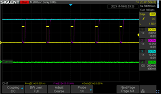
PWM: 25kHz, 3.3V (logic level)
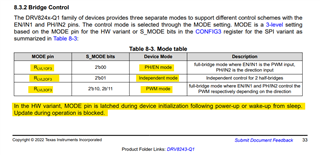
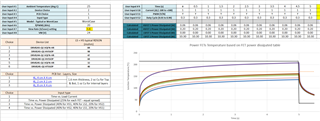
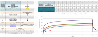
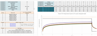
Driver configuration:
-> Mode: PWM Mode -> RLVL3OF3 -> Hi-Z (not connected)
-> ITRIP: aprox. 11 A -> Vitrip:1.18 V -> RLVL2OF6 -> 8.2k ohm
-> SR: 1.6 V/us -> LVL2 -> 8.2k ohm
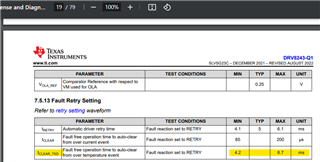
-> DIAG: Fault reaction: Retry -> RLVL1OF6 -> connected to GND
-> PROPI resistor: 330 ohm
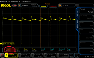
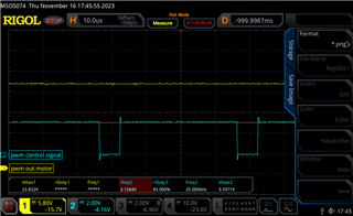
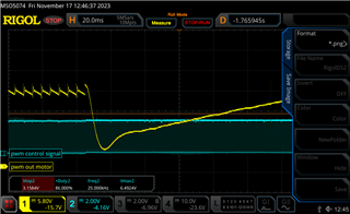
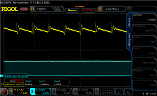
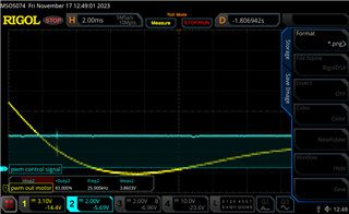
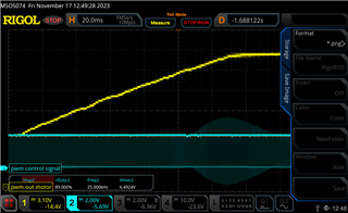
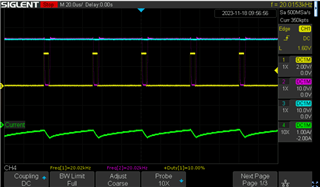
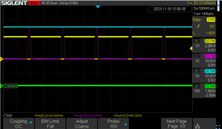
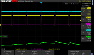
The motor moves, without any noise, when the duty cycle is bigger than 80%, but if the duty cycle goes bellow 80%, the motor stops moving and the driver starts making noise.
We try to use a less powefull power supply (3.3 A) but the results were the same. We checked that the motor draws a little more than 20 A when locked, but since the power supply only allows 20A max, the voltage never goes bellow 24 V and we are using the ITRIP function to regulate the current to 11 A max, we though that we shouldn't have any problem (we are waiting for the DRV8244-Q1 (21 A) to be available on our local market).
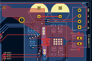
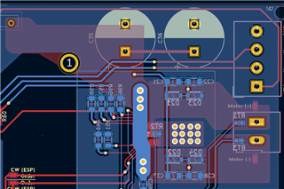
What are we making wrong? Is there something wrong with our schematics or with our driver configuration?
(schematics attached)
Best regards,
João