This thread has been locked.

If you have a related question, please click the "Ask a related question" button in the top right corner. The newly created question will be automatically linked to this question.

DRV8244S-Q1LEVM: ADC Input Conversion to Motor Operating Current

Part Number: DRV8244S-Q1LEVM

Hello,

I am using a DRV8244S-Q1LEVM motor driver which is apart of the VQFN-HR package. I am having some trouble with finding the operating current of a motor based on the ADC in value that is passed in to my MR-CANHUBK344 microcontroller board by the IPROPI pin. My current setup is shown below:

I know that VPROP = RPROP * (DriverOperatingCurrent / AIPROP) from conversations on this previous thread: 

https://e2e.ti.com/support/motor-drivers-group/motor-drivers/f/motor-drivers-forum/1296796/drv8244s-q1levm-spi-control-using-arduino?keyMatch=ANKIT

from my understanding my values are as follows: AIPROP = 4750 A/A, RPROP = 500 Ω

The particular questions I have 

1) How do I measure the driver operating current properly (right now I have a multimeter in series with the Out 1 and Out 2 pins and the motor and it is measuring roughly 0.17 A)

2) How do I make sense of the value I am reading in on FreeMASTER. Currently I have the ADC input settings below:
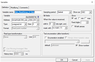
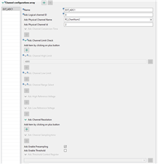
Additionally, below is how the ADC channel is configured within the S32 Configuration Tool with an ADC Channel High Limit of 4095:
My goal for this project is to be able to convert the ADC value that I am reading in on FreeMASTER to a value that is equivalent to how many amps the motor is drawing (hooked up between OUT1 and OUT2). This will allow me to develop controls in based on the value of the motor current.

Best regards,

Bravin Link

  • Hey Bravin,

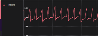
    Is your load a Brushed DC motor?  If so, its current waveform will have ripples like this:

    So the current reading over time could vary widely depending on where in the commutation it is at.  You can use a logic analyzer like Saleae Logic or an oscilloscope to see this effect.

    Because of that I recommend doing your testing with a known resistor value - for example, put in a 10Ω or 100Ω resistor across the output terminals and measure the voltage/current then.  Should be more consistent. 

    Before that, you should try reading a known voltage with your ADC, such as 3.3V or 1.8V (use a AA battery) or similar, and use that to make sure you are correctly converting your ADC reading to a voltage.  With a max of 4096 if its voltage range is 0-3.3V, then it should be Voltage = ADCread*3.3/4096.  Ex if you read 1000 on the ADC that is 1000*3.3/4096 = 0.805V.  

    Unfortunately I'm not familiar with the FreeMASTER or the software you show, so I can't help further with config.  

    Let me know if that helps!

    Best,

    Jacob

  • Hi Jacob,

    I have tried directly injecting a voltage value such as 3v or 1.335v to the ADC in pin and it seems like I am reading the ADC value correctly on FreeMASTER. My issue resides with the output of the IPROPI pin. I have connected a 1k resistor with the IPROPI output so that I can read the current of the operating load as a voltage drop across that 1k resistor. However, when I read the value of the ADC in this case, I do not see any input... I don't have any resistors that you mentioned on hand so I have been continuing to connect a brushed DC motor between out1 and out 2 of the motor driver. I know you mention that there will be fluctuations expected on the IPROPI output, but even with the fluctuations I still expect the ADC value to be present and follow suit. Could my connections on the breadboard I am using be incorrect? Is my external resistance value correct? (says typically between 500 and 5000 ohms) I see that there is RIPROPI header built into the motor driver board... Is is wrong to add an additional external resistor to my circuit or does this header contain the "external resistor"?

    I am currently driving the motor by writing 0b10 to register 09h of the user registers while it is in PWM mode. This in turn makes out1-H and out2-L which indicates that IPROPI will be read on ISNS1 side in the circuit. In short, the motor begins to move when I write to this register but I fail to see any ADC fluctuations in FreeMASTER which accesses the pins value on the microcontroller.

    Also, would you happen to know the max voltage I can provide to an ADC input or is it board dependent because I tried looking on the MR-CANHUBK344 reference manual/HW user manual/SW user manual and have had no luck.

    Any advice is greatly appreciated!

  • Hey Bravin,

    Can you read a voltage on IPROPI test point with a multimeter with your setup? 

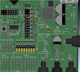
    If you are using the IPROPI resistor jumper then no extra resistor is needed - those resistors are wired directly to the device, then to the test point and J4 as you see in the image below.  I recommend using either the IPROPI resistor header OR an external one, but not both.  I recommend using the EVM header and measuring your voltage at the pin of J4 I pointed out in the image below.  

    ^Note that this screenshot is from Rev A of the EVM (MD047A would be printed above the sticker at the top of the board saying DRV8244S-Q1LEVM).  If your board is Rev E2 or something else let me know and I can confirm the path of the IPROPI trace.  

    Also, would you happen to know the max voltage I can provide to an ADC input or is it board dependent because I tried looking on the MR-CANHUBK344 reference manual/HW user manual/SW user manual and have had no luck.

    This is board-dependent, and should depend on the microcontroller.  Looks like your MR-CANHUBK344 board uses a S32K344 MCU, so look in its datasheet:  https://www.nxp.com/docs/en/data-sheet/S32K3xx.pdf#page=19 looks like 0.3-6V absolute maximum, with 3.3V or 5.0V recommended for VREF_HIGH.  Our device is designed for 0V-3.3V output.  

    Best,

    Jacob