This thread has been locked.

If you have a related question, please click the "Ask a related question" button in the top right corner. The newly created question will be automatically linked to this question.

DRV8718S-Q1EVM: ORVM

Part Number: DRV8718S-Q1EVM

I am trying to control ORVM(Outer rear-view mirrors) Re by establishing  communication  between an Arduino and DRV8718S-Q1 using SPI communication protocol

but motor is not rotating , sometimes output1 and output2 gets same voltage high or low, Pin IN1 and IN2 is varying vice versa as per code , serial monitor displays that the communication established (Motor is rotating ) , kindly give the solution to rotate the motor 

  • Hi Shahajahan,

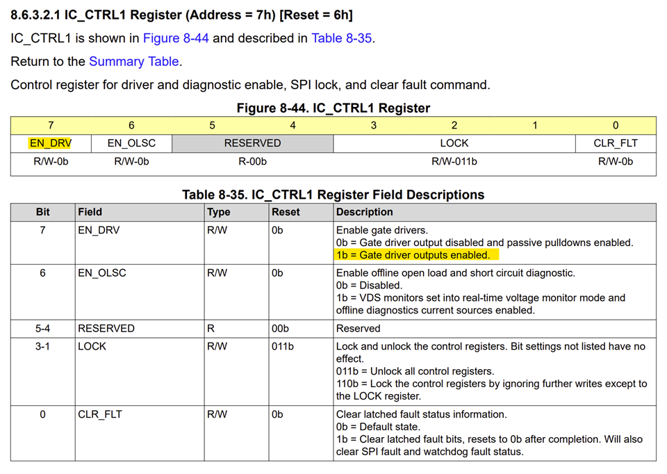
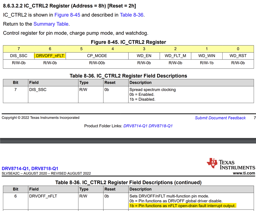
    Did you enable the driver by setting EN_DRV bit to 1 in the IC_CTRL1 register? In addition to this you should have the DRVOFF_nFLT pin to logic LOW if the register bit was selected with default value - the pin is DRVOFF.

    You can also change the DRVOFF_nFLT pin function to nFLT by changing the register bit, see below. When in nFLT it will be an open drain output, an external pull-up resistor must be used with this pin in this mode.

    If these are not correctly configured the bridge output will not be active. 

    Regards, Murugavel

  • Dear expert,

    i am initializing a CS pin  initially it was low and IC_stat1,IC_cntrl1,IC_cntrl2,BRG_cntrl1,IDRV_cntrl1,IDRV_cntrl2 after that CS pin will high in function and it is called in loop , all the OUTPUT port getting high and i am connecting the OUT1 and OUT2 for motor and i am assign the data as per data sheet for control Register 

    i am verified through oscilloscope CS pin were getting Low for long time and High for short time after applying the  delay clock is Low, still motor is not rotating and i am not getting the any one Out1/out2 as low to rotate the motor so kindly resolve the issue asps

  • Dear expert,

    i am using Arduino Mega 2560 as master and remove 0ohm near by J6 connector to control SPI from Arduino and i am connecting the DVDD, nCS, CLK, SDI, SDO, nSleep, nFLT for Power in J2 connecting the power supply 

    any other connection as to be done for rotate the motor?

    here the code 

    void setup()
    {
    SPI.begin();
    pinMode(CS_PIN,OUTPUT);
    pinMode(nSleep,OUTPUT);
    digitalWrite(nSleep,HIGH);
    pinMode(CLK_PIN,OUTPUT);
    pinMode(DVDD,OUTPUT);
    digitalWrite(DVDD,HIGH);

    SPI.beginTransaction(SPISettings(1000,MSBFIRST,SPI_MODE0));


    DRVintialization();

    }

    void loop()
    {
    digitalWrite(CS_PIN,LOW);


    SPI.transfer(0x09);
    SPI.transfer(0x90);// BRG_cntr_1

    SPI.transfer(0x0F);
    SPI.transfer(0x0E);//IDRV_cntrl_1

    SPI.transfer(0x10);
    SPI.transfer(0xDD);//IDRV_cntrl_2

    digitalWrite(CS_PIN,HIGH);

    }

    void DRVintialization()
    {
    digitalWrite(CS_PIN,LOW);

    // Enable the driver
    SPI.transfer(0x00); //status Enable bit
    SPI.transfer(0x80);

    // Unlock the driver
    SPI.transfer(0x07); // IC_Cntrl_1 register address
    SPI.transfer(0x86); // Unlock command

    // Set current control
    SPI.transfer(0x0F); // IDRV_cntrl_1 register address
    SPI.transfer(0x0D); // Current control value

    digitalWrite(CS_PIN,HIGH);


    }

  • Hi Shahajahan,

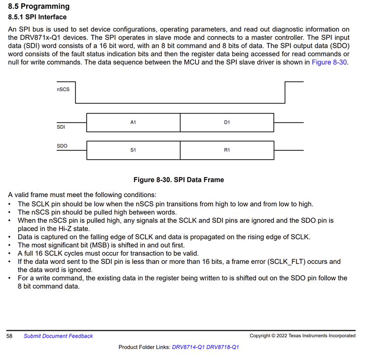
    If you make nSCS LOW and perform multiple SPI register writes (or reads) and then make nSCS HIGH it will not work. None of the registers will be written and will result in SPI error. See below programming information in the datasheet. The nSCS must go LOW for every register write or read and then HIGH before performing another register write or read. 

    The source code for the EVM can be downloaded from EVM webpage. https://dr-download.ti.com/software-development/support-software/MD-GoDz5QXvm0/01.00.00.0B/slvc809b.zip.  

    Regards, Murugavel