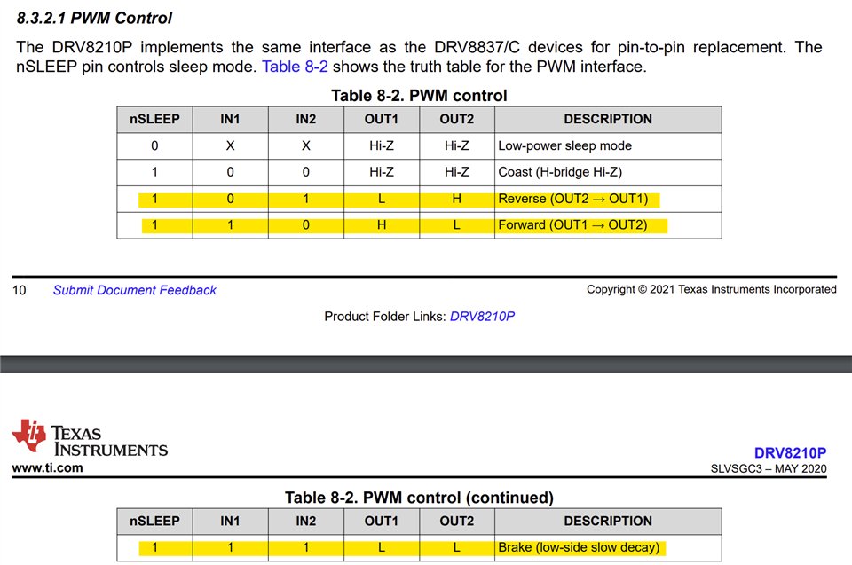
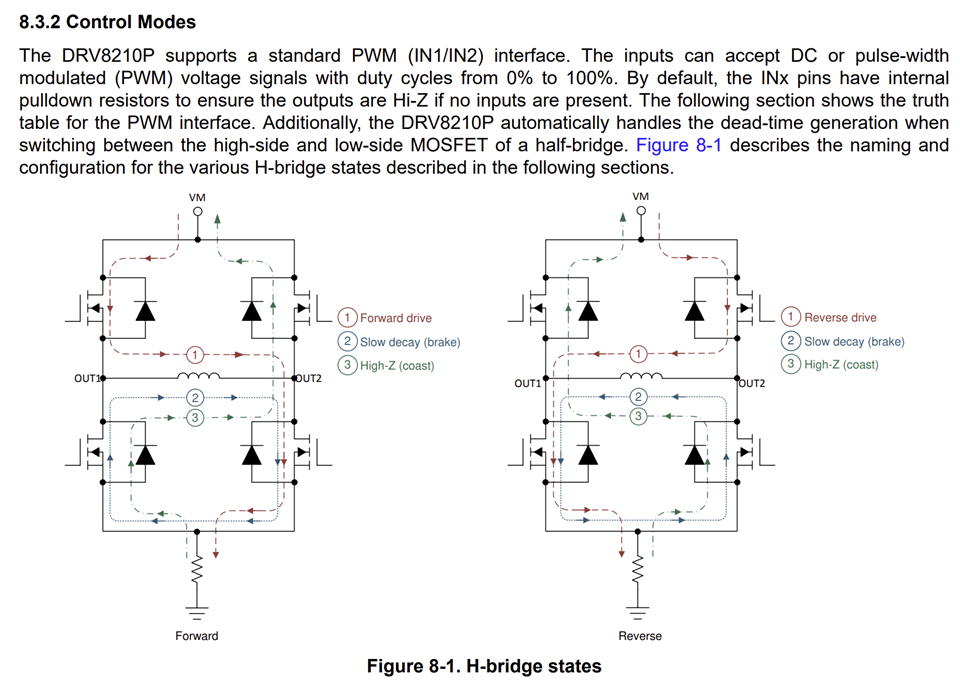
This thread has been locked.

If you have a related question, please click the "Ask a related question" button in the top right corner. The newly created question will be automatically linked to this question.

DRV8210P: DRV8210P

Part Number: DRV8210P

Hello All,

From the datasheet: 

The  DRV8210P datasheet (May 2020) section 8.1 mentions: "With separate motor (VM) and logic (VCC) supplies, the VM voltage can drop to 0 V without significant impact to R DSon and without triggering UVLO as long as the VCC supply is stable".

What happens when the VCC and VM is not split as I see there is a kick back happening when taking the H-bridge from ACTIVE mode to SLEEP mode. Any thoughts on this please? 

I have this part on a single supply and there is a kickback reaching ~3.9V momentarily between ACTIVE to SLEEP mode which is not ideal. 

  • Hi Sasanka,

    What are the conditions under which output voltage pumping is happening. With proper design of BDC motor drive during PWM regulation and while stopping the motor the recirculation current should be set for slow decay - not by making out HiZ which may result in output voltage pumping due to BEMF powering from the running motor. See below control table from the datasheet. This means both IN1 and IN2 must be 1 for motor stop. PWM input works inverse, meaning during PWM = 0 motor runs and PWM = 1 motor current recirculates in the LS-FETs - see image 2. Using this control logic you should not have VM voltage pumping up.

    Regards, Murugavel