This thread has been locked.

If you have a related question, please click the "Ask a related question" button in the top right corner. The newly created question will be automatically linked to this question.

DRV8962EVM: DRV8962EVM

Part Number: DRV8962EVM

Hello Team,

I have a question regarding connections for single solenoid & Gnd connections on EVM.

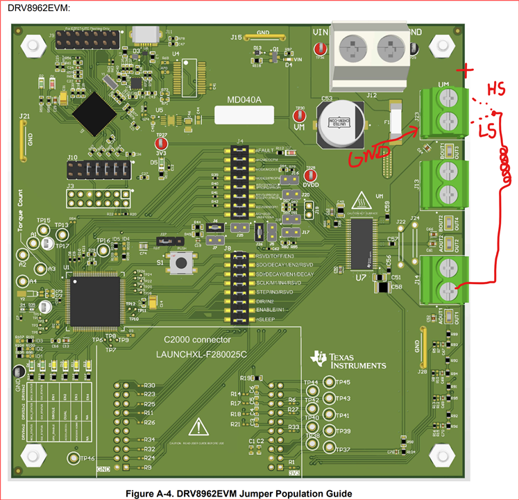
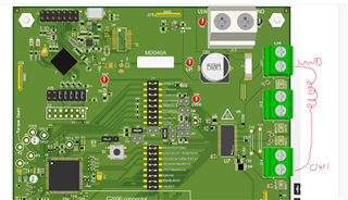
1. How to connect single solenoid to board.. I can see on positive connection on the board from the J14 pin1 and negative connection need to connect on PGND? How to connect it? Through J28,J15 or J21?

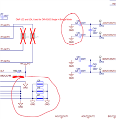
2. How are connecting the Power supply GND & signal GND, I didn't find any short between those in schematics physically?

For question 2, I pasting reference image for GND's, Highligtrhed in the circle.

  • Hi Santhosh,

    1. You can connect the solenoid either as a high side HS or low side LS load. Current sensing is available only with the HS-FET. So if you need current reading on IPROPIx (x = 1 to 4) you must use the low side LS load connection. 

    In the EVM right next to OUT1 to OUT2 terminal there is a power connection terminal with both VM (+) and GND connection. For LS load the solenoid must be connected between OUTx to GND. 

    2. In the EVM, the ground plane has a common Netlist GND for these two ground connections.

    Regards, Murugavel

  • Hello Murugavel,

    As i mentioned One solenoid I am using  one High side

    I1.  will connect my solenoid like this. is it okay?

    2. What is the significance of J15, J21 and J28?

    3. In the datasheet it is return acceptable voltage ripple-- what is TI designed ripple for 48V & 5V?

    Thanks,

    Santhosh

  • Hi Santhosh,

    1. Yes, this is okay to use.

    2. These are GND straps provided for convenience to use with oscilloscope probes or multimeter probes.

    3. For the VM voltage it can tolerate a high ripple. The driver itself will be operational as long as the VM > VMUVLO falling specification. Of course such high ripple will be detrimental to the load. The point is VM is not sensitive to high ripple. Similarly for the VCC, the device will work fine as long as VCC > VCCUVLO falling specification.

    The acceptable ripple would be for the load behavior itself.

    Regards, Murugavel