Hello Murugavel,
I am testing the DRV8962EVM board.
connections details:
1.48V at VM and GND.
2. 3.3V power supply to EN1 and sleep Pin,
3.3V power to VCC and other pins Via USB of the board.
4. connected resistor load across Out1 & GND.
4.I removed all the Jumpers which connected to board Micro controller & DRB8962 IC. as I am using my own controller for PWM.
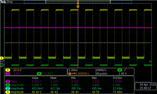
I am facing one issue on the PWM. I connected PWM signal of 1Khz with 50% duty cycle in the IN1 Pin. Following Results are coming.
Here,
CH1 & CH2 top and bottom MOSFETS of OUT1- Half bridge.
CH3 is 48V - VM input signal.
CH4- PWM input to the board.
PWM is not switching as required, Out1 should Switch as the PWM input right.. Why it is not working as intented.
Could you please provide the reply ASAP.
Thanks.
Santhosh.