Tool/software:
Hello.
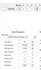
Please tell us the GUI settings for measuring the waveform below.
Original question:

Tool/software:
Hello.
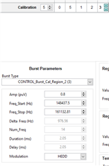
Please tell us the GUI settings for measuring the waveform below.