Other Parts Discussed in Thread: MCF8315C, , MCF8315C-Q1
Tool/software:
I am working with a custom motor with the following specifications:
- 4 poles
- Resistance: 3.4 Ohms
- Inductance: 20 uH
- BEMF Constant: 10 mV/Hz
- Rated current: 500 mA
- Max RPM: 30k (1kHz)
- VM voltage 14V
It is running well in closed loop (with speed loop enabled). MPET helped with tuning Speed_Ki and Speed_Kp. I am using the following PI loops constants:
- Current_Ki = 10000
- Current_Kp = 4
- Speed_Ki = 0.0022
- Speed_Kp = 0.00224
I want now to optimize the MCF8315 parameters, in particular the Current_Ki and Current_Kp which I defined arbitrarily. Doing that I have the following issues:
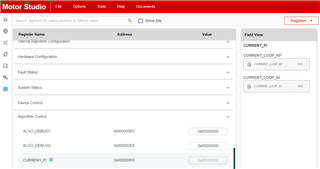
- According Motor Studio and to the IC labeling the IC on the board is the MCF8315C, though it is a 40 pins IC and according to the latests MCF8315C datasheet it only comes with 32 or 24 pins, this also leads to having a single DACOUT documented on the datasheet though there are two available
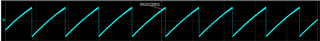
- I am using DACOUT1 and DACOUT2 and it seems they are inverted in the MCF8315EVM test points?
- How to optimize Current_Ki and Current_Kp? As far as I see MPET does not do it and there is no guideline on the application notes, I see though that some values make the closed loop not to work
- Using DACOUT1 and DACOUT2 I am trying to output internal signals for debugging and some (most) seem not to work, for instance PHASE_CURRENT_A, B and C work, but these others do not work: PHASE_VOLTAGE_Vx, THETA_EST
- I moved from MCF8316 to MCF8315 because the available current settings were not suitable for low current motors, with the MCF8315 it has improved but still some settings (like current limits) are not well adapted to my motor, is there another part number that could work better for this current range and that implements FOC?
- While using Motor Studio on the Quick Spin page, some times clicking on the Inductance field makes the inductance value to be displayed in binary (for instance 111111) and then when moving to another field it mistakes that value for an actual entry and replaces it with the maximum inductance (20 mH)
Here is the JSON with all the registers:
{
"signature":"oneui-register-data",
"data":[
[
{
"idx":0,
"id":"ISD_CONFIG",
"value":"0xE4738CA0",
"addr":"0x00000080"
},
{
"idx":1,
"id":"REV_DRIVE_CONFIG",
"value":"0xA8100000",
"addr":"0x00000082"
},
{
"idx":2,
"id":"MOTOR_STARTUP1",
"value":"0x4B6943D4",
"addr":"0x00000084"
},
{
"idx":3,
"id":"MOTOR_STARTUP2",
"value":"0x1507E004",
"addr":"0x00000086"
},
{
"idx":4,
"id":"CLOSED_LOOP1",
"value":"0x975D02B8",
"addr":"0x00000088"
},
{
"idx":5,
"id":"CLOSED_LOOP2",
"value":"0x0BADCB0F",
"addr":"0x0000008A"
},
{
"idx":6,
"id":"CLOSED_LOOP3",
"value":"0x1BA50B27",
"addr":"0x0000008C"
},
{
"idx":7,
"id":"CLOSED_LOOP4",
"value":"0x60C59770",
"addr":"0x0000008E"
},
{
"idx":8,
"id":"REF_PROFILES1",
"value":"0x00000000",
"addr":"0x00000094"
},
{
"idx":9,
"id":"REF_PROFILES2",
"value":"0x00000000",
"addr":"0x00000096"
},
{
"idx":10,
"id":"REF_PROFILES3",
"value":"0x00000006",
"addr":"0x00000098"
},
{
"idx":11,
"id":"REF_PROFILES4",
"value":"0x800D0000",
"addr":"0x0000009A"
},
{
"idx":12,
"id":"REF_PROFILES5",
"value":"0x00000000",
"addr":"0x0000009C"
},
{
"idx":13,
"id":"REF_PROFILES6",
"value":"0x00000000",
"addr":"0x0000009E"
}
],
[
{
"idx":0,
"id":"FAULT_CONFIG1",
"value":"0x1EDA30A6",
"addr":"0x00000090"
},
{
"idx":1,
"id":"FAULT_CONFIG2",
"value":"0x71522088",
"addr":"0x00000092"
}
],
[
{
"idx":0,
"id":"INT_ALGO_1",
"value":"0x8D44C06D",
"addr":"0x000000A0"
},
{
"idx":1,
"id":"INT_ALGO_2",
"value":"0x00000267",
"addr":"0x000000A2"
}
],
[
{
"idx":0,
"id":"PIN_CONFIG",
"value":"0x00000309",
"addr":"0x000000A4"
},
{
"idx":1,
"id":"DEVICE_CONFIG1",
"value":"0x08100000",
"addr":"0x000000A6"
},
{
"idx":2,
"id":"DEVICE_CONFIG2",
"value":"0x03E8D000",
"addr":"0x000000A8"
},
{
"idx":3,
"id":"PERI_CONFIG1",
"value":"0xC0EC5C00",
"addr":"0x000000AA"
},
{
"idx":4,
"id":"GD_CONFIG1",
"value":"0x984E1903",
"addr":"0x000000AC"
},
{
"idx":5,
"id":"GD_CONFIG2",
"value":"0x00840000",
"addr":"0x000000AE"
}
],
[
{
"idx":0,
"id":"GATE_DRIVER_FAULT_STATUS",
"value":"0x00000000",
"addr":"0x000000E0"
},
{
"idx":1,
"id":"CONTROLLER_FAULT_STATUS",
"value":"0x00000000",
"addr":"0x000000E2"
}
],
[
{
"idx":0,
"id":"ALGO_STATUS",
"value":"0x00000004",
"addr":"0x000000E4"
},
{
"idx":1,
"id":"MTR_PARAMS",
"value":"0xCC0F0F00",
"addr":"0x000000E6"
},
{
"idx":2,
"id":"ALGO_STATUS_MPET",
"value":"0x1A000000",
"addr":"0x000000E8"
}
],
[
{
"idx":0,
"id":"ALGO_CTRL1",
"value":"0xAA500000",
"addr":"0x000000EA"
}
],
[
{
"idx":0,
"id":"ALGO_DEBUG1",
"value":"0x80000000",
"addr":"0x000000EC"
},
{
"idx":1,
"id":"ALGO_DEBUG2",
"value":"0x00000021",
"addr":"0x000000EE"
},
{
"idx":2,
"id":"CURRENT_PI",
"value":"0x03010301",
"addr":"0x000000F0"
},
{
"idx":3,
"id":"SPEED_PI",
"value":"0x031703ED",
"addr":"0x000000F2"
},
{
"idx":4,
"id":"DAC_1",
"value":"0x0000375C",
"addr":"0x000000F4"
},
{
"idx":5,
"id":"DAC_2",
"value":"0x00040440",
"addr":"0x000000F6"
}
],
[
{
"idx":0,
"id":"ALGORITHM_STATE",
"value":"0x00000000",
"addr":"0x00000190"
},
{
"idx":1,
"id":"FG_SPEED_FDBK",
"value":"0x7FFFFFFF",
"addr":"0x00000196"
},
{
"idx":2,
"id":"BUS_CURRENT",
"value":"0x00000000",
"addr":"0x00000410"
},
{
"idx":3,
"id":"PHASE_CURRENT_A",
"value":"0x00000000",
"addr":"0x00000440"
},
{
"idx":4,
"id":"PHASE_CURRENT_B",
"value":"0x00000000",
"addr":"0x00000442"
},
{
"idx":5,
"id":"PHASE_CURRENT_C",
"value":"0x00000000",
"addr":"0x00000444"
},
{
"idx":6,
"id":"CSA_GAIN_FEEDBACK",
"value":"0x00010000",
"addr":"0x00000468"
},
{
"idx":7,
"id":"VOLTAGE_GAIN_FEEDBACK",
"value":"0x00000001",
"addr":"0x00000472"
},
{
"idx":8,
"id":"VM_VOLTAGE",
"value":"0x01DF4000",
"addr":"0x00000476"
},
{
"idx":9,
"id":"PHASE_VOLTAGE_VA",
"value":"0x0003E5A9",
"addr":"0x0000047A"
},
{
"idx":10,
"id":"PHASE_VOLTAGE_VB",
"value":"0x0003E5A9",
"addr":"0x0000047C"
},
{
"idx":11,
"id":"PHASE_VOLTAGE_VC",
"value":"0x0003E5A9",
"addr":"0x0000047E"
},
{
"idx":12,
"id":"SIN_COMMUTATION_ANGLE",
"value":"0x00000000",
"addr":"0x000004B6"
},
{
"idx":13,
"id":"COS_COMMUTATION_ANGLE",
"value":"0x00000000",
"addr":"0x000004B8"
},
{
"idx":14,
"id":"IALPHA",
"value":"0x00000000",
"addr":"0x000004D2"
},
{
"idx":15,
"id":"IBETA",
"value":"0x00000000",
"addr":"0x000004D4"
},
{
"idx":16,
"id":"VALPHA",
"value":"0x00000000",
"addr":"0x000004D6"
},
{
"idx":17,
"id":"VBETA",
"value":"0x00000000",
"addr":"0x000004D8"
},
{
"idx":18,
"id":"ID",
"value":"0x00000000",
"addr":"0x000004E2"
},
{
"idx":19,
"id":"IQ",
"value":"0x00000000",
"addr":"0x000004E4"
},
{
"idx":20,
"id":"VD",
"value":"0x00000000",
"addr":"0x000004E6"
},
{
"idx":21,
"id":"VQ",
"value":"0x00000000",
"addr":"0x000004E8"
},
{
"idx":22,
"id":"IQ_REF_ROTOR_ALIGN",
"value":"0x00000000",
"addr":"0x00000524"
},
{
"idx":23,
"id":"SPEED_REF_OPEN_LOOP",
"value":"0x00000000",
"addr":"0x0000053C"
},
{
"idx":24,
"id":"IQ_REF_OPEN_LOOP",
"value":"0x00000000",
"addr":"0x0000054C"
},
{
"idx":25,
"id":"SPEED_REF_CLOSED_LOOP",
"value":"0x00000000",
"addr":"0x000005D4"
},
{
"idx":26,
"id":"ID_REF_CLOSED_LOOP",
"value":"0x00000000",
"addr":"0x00000606"
},
{
"idx":27,
"id":"IQ_REF_CLOSED_LOOP",
"value":"0x00000000",
"addr":"0x00000608"
},
{
"idx":28,
"id":"ISD_STATE",
"value":"0x00000000",
"addr":"0x00000682"
},
{
"idx":29,
"id":"ISD_SPEED",
"value":"0x00000000",
"addr":"0x0000068C"
},
{
"idx":30,
"id":"IPD_STATE",
"value":"0x00000000",
"addr":"0x000006C0"
},
{
"idx":31,
"id":"IPD_ANGLE",
"value":"0x00000000",
"addr":"0x00000704"
},
{
"idx":32,
"id":"ED",
"value":"0x00000000",
"addr":"0x0000074A"
},
{
"idx":33,
"id":"EQ",
"value":"0x00000000",
"addr":"0x0000074C"
},
{
"idx":34,
"id":"SPEED_FDBK",
"value":"0x00000000",
"addr":"0x0000075A"
},
{
"idx":35,
"id":"THETA_EST",
"value":"0x00000000",
"addr":"0x0000075E"
}
]
]
}