This thread has been locked.

If you have a related question, please click the "Ask a related question" button in the top right corner. The newly created question will be automatically linked to this question.

LP-MSPM0G3507: MSPM0 Sensorless FOC Software damages BOOSTXL-DRV8323RS

Part Number: LP-MSPM0G3507
Other Parts Discussed in Thread: BOOSTXL-DRV8323RS, CSD88584Q5DC

Tool/software:

Hello,

I am running MSPM0 Sensorless FOC from SDK 2.1.0.03. The motor startup works quite well until one of the BOOSTXL-DRV8323RS MOSFETs (C1 or C2 or C3) shows signs of a thermal event. This happened now to two boards and I am a bit puzzled as the operation is well within the bounds I know about.

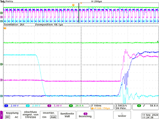
The system is supplied with 30 V and about 5 A while the motor is running stable, as far as I can judge by the sound of it. This should be well within the limits as it is less than 48 V and less than 15 A. However, after some seconds the thermal event takes place and one of the MOSFETs starts smoking. The motor stops spinning and the following status information is shown:

systemFaultStatus: 0 (NO_FAULTS)
motorState: 6 (MOTOR_ALIGN)

I set up my system in accordance with the tuning guide in preparation for Open Loop Debug, which led to the following adjustments:

pUserInputRegs->mtrStartUp1.b.mtrStartUpOption     = 0; // Motor start-up method Align
pUserInputRegs->mtrStartUp1.b.olILimitCfg          = 0; // Open loop current limit defined by OL_ILIMIT
pUserInputRegs->mtrStartUp2.b.olILimit             = 0x05; // Open loop current limit at 10 % * FULL_SCALE_CURRENT_BASE
pUserInputRegs->faultCfg2.b.maxVmMtr               = 0x3;  // Voltage maximum at 75 % * voltageBase
pUserInputRegs->faultCfg2.b.minVmMtr               = 0x0;  // No voltage minimum
pUserInputRegs->isdCfg.b.isdEn                     = 0; // Start with standstill
pUserInputRegs->systemParams.mtrResist             = 39; // 38.5 mOhm
pUserInputRegs->systemParams.mtrInductance         = 17; // 16.95 µH
pUserInputRegs->systemParams.mtrBemfConst          = 167; // 16.717 mV/Hz
pUserInputRegs->systemParams.currLoopKp            = 0; // Auto compute
pUserInputRegs->systemParams.currLoopKi            = 0; // Auto compute
pUserInputRegs->systemParams.mtrSaliency           = 0.0548;
pUserInputRegs->systemParams.voltageBase           = 57.42; // 57.42 V
pUserCtrlRegs->algoDebugCtrl1.b.closeLoopDis       = 1;    // run in open loop only for Motor Open Loop Debug
pUserCtrlRegs->algoDebugCtrl2.b.currLoopDis        = 1;    // disapble current loop only for Motor Open Loop Debug
pUserCtrlRegs->algoDebugCtrl2.b.forceVDCurrLoopDis = 100;  // starting point for tuning
pUserCtrlRegs->algoDebugCtrl2.b.forceVQCurrLoopDis = 100;  // starting point for tuning
pUserCtrlRegs->speedCtrl.b.speedInput              = 500;
#define FULL_SCALE_CURRENT_BASE                    23.571
#define MOTOR_MAX_SPEED                            833.0

I would like to prevent losing more hardware. Is there anything I am missing?

  • Hi,

    Let me check with out motor control expert about your question. 

    Best regards,

    Cash Hao

  • Hi Tobias,

    Sorry for late response here.

    I see you are working in pwm loop mode, which means you will control your motor with an fixed pwm duty cycle. 

    One possible reason is that the deadtime for MOSFET is not enough for this. would you try to incrase your deadtime setting to see whether the issues still exsit.

    Meanwhile, you can also share the current waveform for the motor. I am not sure what the 5A is...If this is power supply current consumption, then the phase current should be much higher than this.

    B.R.

    Sal

  • Hi Sal,
    we appreciate your response.

    The dead time is now set to 500 ns for a generous gap, as we think: 

    Legend:
    1. Voltage between HS gate and source (differential)
    2. Voltage between LS gate and source
    3. Voltage phase
    4. Current phase

    Looking closely at the waveforms, we see issues that can be explained with an unsuitable configuration of the gate driver. The measurement shows a jumping LS gate signal which probably leads to the LS MOSFET closing while the HS MOSFET is just opening. We consider this a brief short circuit. However, we would need to setup a more elaborate measurement to be sure.

    In order to rule out other factors that are more efficient to be examined, we targeted the phase voltage that appeared surprisingly low during ramp up with about 15 V. We increased the power supply limit to 15 A (still within bounds dev.ti.com/.../DRV8323RS_Hardware_User_Guide.html) and reduced olILimit to 7,5 %. However, this had little effect and we damaged yet another electronics, showing the same pattern as described above.

    As our ressources are coming to an end here, we wonder if there is anything else we could do in the remaining time. However, we are under the impression that our motor is too much of a load and unsuitable for the gate driver configuration. We assume that both cannot be solved in time as the olILimit does not provide sufficient control and preparing another motor just to try yet another one after is beyond what we can invest. Apart from that, tuning the gate driver is a challenge in itself that is beyond as well. Are there more efficient steps that could eventually lead to the promised quick success?

  • Hi Tobias,

    Several suggestions from my side.

    1.Please also show the phase current waveform of a complete electrical cycle, and currently it only shows several PWM duty cycles' waveform. It will be better to give a overall current waveform for reference.

    2.For the waveform you showed here, the phase current at least has nearly 60A peak value, then it means its RMS value is 60/sqrt(2)=42A. This is within the MOSFET spec, if this is the peak value. -> Then please make sure the deadtime is sufficient for these high current, usually it requires 1-2us for high current, or even larger.

    [CSD88584Q5DC 40V Half-Bridge NexFET Power Block datasheet]

    3. Current base and current limitation

    reduced olILimit to 7,5 %. However, this had little effect and we damaged yet another electronics,

    Due to customer does not use current loop mode, then the current limitation is not work here.

    Line 15 "pUserCtrlRegs->algoDebugCtrl2.b.currLoopDis        = 1;    // disapble current loop only for Motor Open Loop Debug" shows the scenario.

    On the other hand, I am not sure your current base setting is, I don't find it in your shared code. While, according to the macro definition "FULL_SCALE_CURRENT_BASE" here, this means your phase current should not exceed 23.571A. And, the 60A phase current is out of the detection scale range. It might be okay for customer, due to customer only using pwm mode without performing any speed loop or current loop control.

    4. Suggestion on further tuning method.

    As our ressources are coming to an end here, we wonder if there is anything else we could do in the remaining time.

    Why customer need using PWM control mode (disable close loop, disable current loop)? It is less efficient and the current is not controlled in algorithm.

    If no requirement for closeloop, using current loop for your application.

    Remove below:
    pUserCtrlRegs->algoDebugCtrl2.b.currLoopDis        = 1;    // disapble current loop only for Motor Open Loop Debug
    pUserCtrlRegs->algoDebugCtrl2.b.forceVDCurrLoopDis = 100;  // starting point for tuning
    pUserCtrlRegs->algoDebugCtrl2.b.forceVQCurrLoopDis = 100;  // starting point for tuning
    
    Add below for current control:
    pUserInputRegs->mtrStartUp1.b.alignOrSlowCurrLimit -> set align current
    pUserInputRegs->mtrStartUp2.b.olILimit -> set open loop current
    pUserInputRegs->mtrStartUp2.b.olClHandOffThr -> set the open loop speed

    B.R.

    Sal