Tool/software:
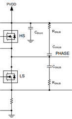
I am designing a BLDC driver. The phase outputs oscillate and I plan to add RC snubber circuits to the upper and lower FETs of the half bridge. I would like to follow the design guidelines for a 7-stage RC snubber circuit as described in this topic.
I have a few questions:
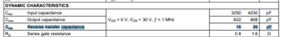
The rectifier has a capacitor value of 22pF, where is this listed on the CSD18540Q5B MOSFET datasheet? I could not find this value in the published datasheet.
To find the parasitic inductance, should the extra capacitor C1 be added to the top FET or the bottom FET? Should I add it to both FETs or just one?
Sorry for the basic question and the bad English.