DRV8955: SN754410 to DRV8955 upgrade

Part Number: DRV8955
Other Parts Discussed in Thread: SN754410, LM339, NE555, LM393, DRV8962

Tool/software:

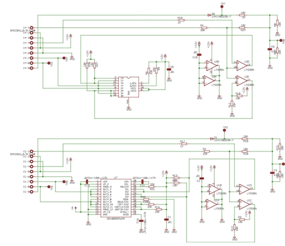
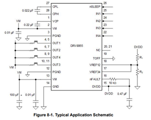
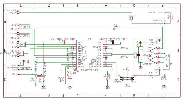
I believe I found an excellent choice for upgrading my motor driver however, no reference design exists and I couldn’t find one schematic that uses it, I studied the data sheet and came up with a possible solution.

The top circuit is my tried and true low power SN754410 motor driver and the bottom circuit is the potential higher power driver using the DRV8955.

If something isn’t right or needs adjustment let me know, if it won’t work and you know why I would appreciate the help since it’s been more than 20 years since I’ve done anything in this field so I’m kinda lost and looking for help.

  • Hi Dale,

    There is a Typical Application section in the datasheet that shows how to connect external components for a typical application.

    Another thing that we recommend to all designers and engineers looking to evaluate our motor drivers is to order an evaluation module (EVM). This EVM is a great ready-to-use platform for evaluating different components, refine the design, and evaluate the performance of the motor driver.

    DRV8955PEVM Evaluation board | TI.com 

    Within the product portfolio page (linked above) you will find links to the hardware and software files for download. These will give you access to all the PCB design files, schematics, etc. as well as the firmware that is used.

    Best,

    David

  • I am a hobbyist at best with the resources to bring to light projects I work on.

    My reason for coming here is to get some help from someone(s) with the knowledge and experience to help me solve my power problem, yes i have stacked the SN754410 to get more power out of it but this is band aid and not a real solution.

    The EVM board is pretty to look at it uses an mcu and software which makes it unsuitable and any result based on the EVM wouldn't be applicable unless I added the MCU to my project and adding more complication to the schematic and, because all software has bugs and flaws it would take time to get it reliably battle ready, not to mention add six months or more to my project which in a business sense the time is probably reasonable but as a personal project waiting six months (longer) performing tests and interpreting results (which I'm clueless about) to come up with a driver I can build and use in a couple of days from now.

    The SN754410 schematic is one I snagged from a freeware project and didn't have to do anything but plug it in to my circuit project to have it operational and I can't find one schematic aside from the EVM that I can plug in which is disappointing.

    it would be nice if TI made a 5A version of the SN754410 that I could just plug in to get the power I require but that is wishful thinking.

    So it appears that a simple. non MCU design that I could plug in doesn't exist and no one can tell me if the values I selected for resistors/capacitors are suitable or share a schematic that operates a DC motor (out1/2 and out3/4).

    The motor will operate from +48VDC, the comparator and SSR operate from +12VDC so both voltages are available, the NE555 drives the comparator LM339 (soon to be LM393) the MODE pin I believe should be 330K to GND so I can parallel the inputs/outputs to keep things simple and not worry, about VREF's however, if MODE would be better as 1, a schematic with correct values that reflects this MODE would be required so I can integrate it quickly into my schematic and produce my PCB.

    In a former life I worked in a PCB shop and have created mini versions of the equipment to produce professional quality PCB's up to 17x11 at home and I made a small reflow oven to handle SMD components so I have resources and tools to achieve my goals however, I'm no engineer and this is my weak point.

  • The circuit example doesn't use the RSVD/EN1 or MODE pins and ties TOFF/EN2 to GND which I'm assuming is always enabled and I can accept this so what values would I use for R1/R2 assuming the motor is 3A peak or 4A peak?

    Is auto reset also enabled in this configuration or do I need to add a switch to nSLEEP (nSLEEP=1) to clear the overcurrent fault or does this prevent overcurrent so the error never occurs?

  • Hi Dale,

    TI offers a wide portfolio of motor drivers to fit many applications. From your description it sounds like it would be worth looking into the DRV8962.

    This device has a hardware interface, so no MCU is required. It has a 70V abs max which gives you plenty of headroom for your 48V motor. It also is a single or dual H-bridge or quad half-bridge driver with integrated current sensing. This motor driver might help to simplify your design. 

    DRV8962-Q1 data sheet, product information and support | TI.com 

    Best,

    David

  • Hi David, I did look at this as an option but again, I couldn't find a schematic that didn't use an MCU/Controller (block diagram) and, IPROP added confusion as I couldn't find a schematic that didn't use a controller to manage them so to me it isn't suitable.

    The DRV8955 seems to be more suitable or easier to implement, I still have the R1/R2 values to figure out but what concerns me is that two VM pins on the device with trace thickness of 0.4mm are going to handle 10A, I don't see how since there isn't enough area to support this.

    Attached are my schematic and board.

  • Hi,

    Thank you for your questions. Our expert will feedback to you within a day or two business day.

  • Hi Dale,

    How much current are you looking to drive, 10A? Is this a peak current value or are you looking to drive 10A continuously? 

    If you tie a 330kΩ resistor between MODE and GND, you will be able to operate all four half-bridges independently; however, this also means you will not be able to have any current regulation. Without current regulation, the overcurrent protection (IOCP) will trip after the load has drawn over 16A for about 2us. It is also worth noting that if this much current is being driven continuously the device will get hot and could reach the thermal shutdown temperature, which occurs when the die reaches 150C. 

    It is always recommended to use current regulation when possible. Using current regulation not only helps protect the load but also helps against inrush current when driving a brushed-DC motor. 

    The MODE pin can have four different configurations. These configurations will also change the IOCP trip points by changing the transimpedance gain of the device. These values can be found in the datasheet under the Electrical Characteristics section.

    Keep in mind if using current regulation, it is recommended to keep the ITIP threshold well below the IOCP threshold, so the device doesn't accidentally reach the overcurrent protection threshold. 

    The following formula can be used for current regulation to set the ITRIP threshold. Keep in mind this formula changes based on the MODE pin. 

    Best,

    David