This thread has been locked.

If you have a related question, please click the "Ask a related question" button in the top right corner. The newly created question will be automatically linked to this question.

DRV8889-Q1: STL and FAULT did not set to 1 when TRQ_COUNT is less than STALL_TH

Part Number: DRV8889-Q1

Tool/software:

Hi team,

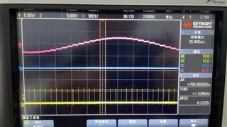
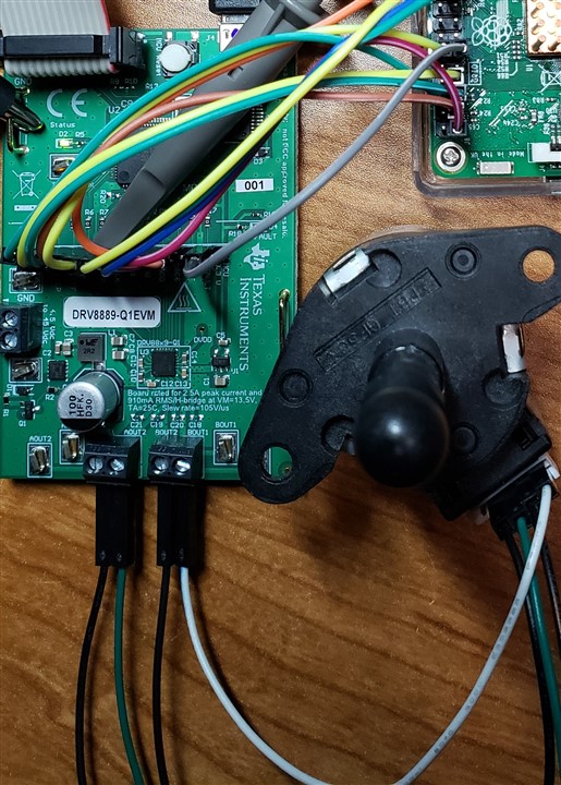
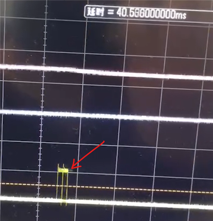
As the video shows, customer let 8889 learn the STALL_TH value to 0x17, and test stall condition. When TRQ_COUNT = 0x11, the STL and FAULT bit did not set to 1 which does not match the datasheet. Could you please help analyze what's the problem?

BR,

Bengi

  • Hi Bengi,

    How is the STEP input provided to the DRV8889-Q1. If there is step to step pulse width variation then the detection logic will be masked and not work. Can you confirm if the STEP pulses were consistent pulse to pulse during the test including no acceleration or deceleration of step rate happening? Thanks.

    Regards Murugavel 

  • Hi Murugavel,

    As shown below, the STEP pulses are stable (yellow). Red = A1, and Blue=DIR. Is there any reason that will cause above problem?


    This case happened in Customer's module, and I will let him test our EVM module too.

    BR,

    Bengi

  • Hi Bengi,

    Could you please share the stepper motor datasheet or motor L and R parameters, VM voltage, IFS current setting, uStep mode, step rate PPS used for the test? 

    As shown below, the STEP pulses are stable (yellow). Red = A1, and Blue=DIR. Is there any reason that will cause above problem?

    Please measure time period for every step pulse and verify if they are same or there is even a small variation. Thanks.

    This case happened in Customer's module, and I will let him test our EVM module too.

    Sounds good, thanks.

    Regards, Murugavel 

  • Hi Murugavel,

    Motor datasheet is attached.

    PL35-VHP2_S00018410 (REV.E) Spec sheet.pdf

    Please measure time period for every step pulse and verify if they are same or there is even a small variation. Thanks.

    As you can seen in below video, the step pulse is stable.

    BR,

    Bengi

  • Hi Bengi,

    This stepper motor is known to work well with the DRV8889-Q1 stall detection. Please see the video in the zip file. Testing PL35 stepper in headlight assembly using a DRV8889-Q1EVM. The GUI settings are shared in the zip file as well.

    HL Stepper DRV8889-Q1EVM Demo 0421.zip

    Regards, Murugavel 

  • Hi Murugavel,

    Yes, I know it can work well with our stepper motor driver, and customer also did test in EVM and verify this. What's important is, it cannot work well in customer's module. I can't just tell him: "it can work well in our EVM so it is your problem". Please help find what is the root cause for this. I have attached the step pulse before, please check that video.

    BR,

    Bengi 

  • Besides, in our EVM user guide there's no schematic information. Could you please offer me that? Customer wants to do comparison. Thanks

    BR,

    Bengi

  • Hi Bengi,

    Yes, I know it can work well with our stepper motor driver, and customer also did test in EVM and verify this. What's important is, it cannot work well in customer's module.

    Of course, this is part of the debug process. You did not mention until now that customer did test with EVM with their motor and stall detection worked. the last update you had regarding this was;

    This case happened in Customer's module, and I will let him test our EVM module too.
    I can't just tell him: "it can work well in our EVM so it is your problem". Please help find what is the root cause for this.

    Nowhere I mentioned the way you phrased it. I'm trying to help you debug the issue. Working with the EVM is a comparison data point that DRV8889-Q1 supports stall function with their motor and their application operating conditions. This will allow us debug other things in their system, we don't need to focus on the motor or its operating condition such as step rate and ustep setting used. 

    Now that you've mentioned customer was able to verify their motor stall detection works with EVM there is one additional check they can do with their board combining with the EVM. Setup the EVM GUI with the desired step rate and connect the STEP pulses from the EVM header to the customer's PCB. They can retain all other communications using their MCU and check for stall functionality. 

    The reason for requesting this verification is, the STEP input has internal step frequency filtering for stall detection to avoid false stall detection during acceleration and deceleration of the STEP pulses which is standard behavior.

    As you can seen in below video, the step pulse is stable.

    Reviewing the video it appears there is pulse to pulse period variation. In the beginning of the video I noticed 29 ms, then I noticed 30, 31, 32, 33,....46 ms. I hope I was reading the time measurement correctly. Also at one point there was a double capture suggesting a large jitter.

    Besides, in our EVM user guide there's no schematic information. Could you please offer me that? Customer wants to do comparison.

    The EVM schematics and complete Altium project with source files are available for download from the EVM webpage, https://www.ti.com/tool/DRV8889-Q1EVM.


    Regards, Murugavel 


  • Hi Murugavel,

    Thanks for your reply. Now I and customer verified that if we use a signal generator as input to STEP, the stall can be detected. In customer's board, their STEP variation is 700us(±3us), is this the reason that customer cannot detect stall condition?

    BR,

    Bengi

  • Hi Bengi,

    Now I and customer verified that if we use a signal generator as input to STEP, the stall can be detected.

    Thanks for this update. We're going in the right direction.

    In customer's board, their STEP variation is 700us(±3us), is this the reason that customer cannot detect stall condition?

    Yes this is the reason the DRV8889-Q1 is not detecting a stall. All the customers I've worked with are using STEP pulses generated by hardware such as Timer pulse generator or Time PWM integrated in an MCU. This will help avoid step to step period variation. 

    Regards, Murugavel 

  • Hi Murugavel,

    What is the allowable margin of variation for STEP signal? their STEP variation is 700us(±3us), is this variation within the allowable margin?

    BR,

    Bengi

  • Hi Bengi,

    What is the allowable margin of variation for STEP signal? their STEP variation is 700us(±3us), is this variation within the allowable margin?

    Did stall detection work for the customer with the STEP signal that had 700 us variation? My understanding was it did not work. But it worked with a stable STEP input, correct?

    What is the customer's STEP input time period? We need to know this to see how much is 700 us out of that time. The variation should be < 2% of the STEP time period. Based on the first scope capture it appears the customer's STEP period was ~ 0.7 ms, so 2% of that would be 14 us.

    Regards, Murugavel