Tool/software:
Dear Expert
Could u hlep to check
1.Is the waveform normal? Can it be further optimized and improved?
2.Can the operating noise of the motor be optimized?
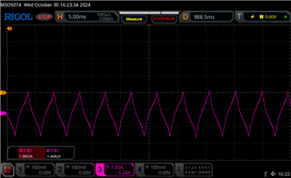
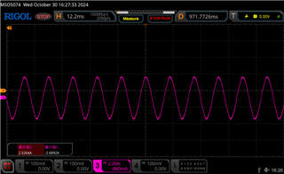
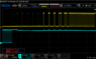
Motor's A1 &B1 voltage waveform
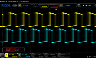
Motor's A1 &B1 voltage waveform
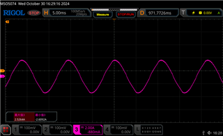
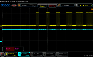
A1 zoom in
Original question:

Tool/software:
Dear Expert
Could u hlep to check
1.Is the waveform normal? Can it be further optimized and improved?
2.Can the operating noise of the motor be optimized?
Motor's A1 &B1 voltage waveform
Motor's A1 &B1 voltage waveform
A1 zoom in