


Tool/software:
Dear TI Engineers, Hello.
We tried to draw the MCF8329A PCB by ourselves, limited by the size and layout of the board, the space given is relatively small, the problem is that the same program on our board the motor does not rotate smoothly and the load capacity is very weak, it is easy to trigger an error and then the motor stops, but the demo board can run normally and has a strong load capacity. From the point of view of phase current, the current crest of our board is irregular. At the beginning, we separated the ground of each chip by magnetic beads, but found that the motor rotated worse, we removed the magnetic beads and found that it was much better, but the load capacity was still very poor, we changed the sampling resistance from 1mr to 5mr, and the load capacity has been improved to a certain extent, but it is still far inferior to the demo board. Later, we also tried external 3.3V, front-end capacitors, etc., the effect is not ideal, we think that there is a problem with our layout, I hope that TI engineers can help see what the problem is, we really can't solve it ourselves---
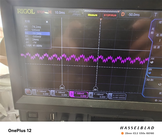 This is the waveform of the demo board, which is very regular.
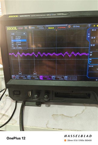 This is our own PCB, the waveform is irregular and there are bumps.8329A-1-16.PcbDocThis is the PCB of the motor part, please refer to it
