This thread has been locked.

If you have a related question, please click the "Ask a related question" button in the top right corner. The newly created question will be automatically linked to this question.

BOOSTXL-DRV8323RS: 1XPWM & TRAPEZOIDAL CONTROL 3 PHASE BLDC

Part Number: BOOSTXL-DRV8323RS
Other Parts Discussed in Thread: DRV8323, DRV8353

Tool/software:

Hi,

I am trying to run a 3-phase BLDC motor using the DRV8323 driver in 1xPWM mode with a Hall effect sensor. I am also using the Nucleo WB55RG board to generate a 20kHz PWM signal.

The motor is spinning, but there is audible noise, which decreases only at a 50% duty cycle. Additionally, the motor speed does not vary with changes in the duty cycle.

INHC= HIGH

INLC = HIGH
INHA = PWM
INLA,INHB,INLB = HALL sensor
ENABLE = HIGH

  • Hi Jay,

    Today is a holiday in the US, but we will aim to provide a response by the end of the week.

    Regards,

    Anthony Lodi

  • Hi Jay,

    Are you using INHC to control the direction? If not it should be tied LOW.

    Audible noise can sometimes arise from uneven commutation or low-resolution PWM signals. Have you used any other PWM frequency other than 20kHz?

    Have you confirmed that the Hall sensor commutation signals align perfectly with the motor phases? You could also check for voltage or current ripple on the power supply lines?

    As for the duty cycle issue have you confirmed that the Nucleo board is actually updating the duty cycle?

    Regards,

    Yara

  • Hi Yara,

    I have set the INHC pin to high to control the motor direction, and the Hall sensor is connected directly to the motor driver. The duty cycle is also updating correctly.

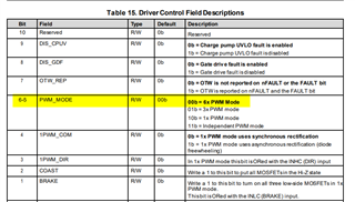
    However, I suspect that there might be an issue with my SPI communication. Does the motor driver need to be explicitly set to 1xPWM mode using SPI, or is it in 1xPWM mode by default?

    Thank you for your help!

  • Hi Jay,

    Thanks for the additional info!

    The default SPI setting for PWM mode is 6x PWM

    So if you're trying to implement 1xPWM without configuring that SPI register that could very well be what the issue is, let know your results when this is fixed.

    Regards,

    Yara

  • Hi Yara,

    I think my SPI configuration have an issue because when I try to read back the control register 0x02 it send a data: 0x0000 and read: 0. Here is my SPI configuration

    SPI:

    static void MX_SPI1_Init(void)
    {
      hspi1.Instance = SPI1;
      hspi1.Init.Mode = SPI_MODE_MASTER;
      hspi1.Init.Direction = SPI_DIRECTION_2LINES;
      hspi1.Init.DataSize = SPI_DATASIZE_16BIT;
      hspi1.Init.CLKPolarity = SPI_POLARITY_LOW;
      hspi1.Init.CLKPhase = SPI_PHASE_2EDGE;
      hspi1.Init.NSS = SPI_NSS_SOFT;
      hspi1.Init.BaudRatePrescaler = SPI_BAUDRATEPRESCALER_2;
      hspi1.Init.FirstBit = SPI_FIRSTBIT_MSB;
      hspi1.Init.TIMode = SPI_TIMODE_DISABLE;
      hspi1.Init.CRCCalculation = SPI_CRCCALCULATION_DISABLE;
      hspi1.Init.CRCPolynomial = 7;
      hspi1.Init.CRCLength = SPI_CRC_LENGTH_DATASIZE;
      hspi1.Init.NSSPMode = SPI_NSS_PULSE_DISABLE;
      if (HAL_SPI_Init(&hspi1) != HAL_OK)
      {
        Error_Handler();
      }
    
    }

    write SPI:

    void DRV8323_writeSpi(uint16_t regAdr, uint16_t regVal)
    {
        uint16_t controlword = ((regAdr << 11) | regVal);  // Create control word
    
        char debugMsg[50];
        HAL_GPIO_WritePin(GPIOA, GPIO_PIN_4, GPIO_PIN_RESET);
        HAL_StatusTypeDef status = HAL_SPI_Transmit(&hspi1, (uint8_t*)(&controlword), 1, 20);
        HAL_GPIO_WritePin(GPIOA, GPIO_PIN_4, GPIO_PIN_SET);
    
        HAL_Delay(90);  
        snprintf(debugMsg, sizeof(debugMsg), "Write Status: %d, Data: 0x%04X\r\n", status, controlword);
        HAL_UART_Transmit(&huart1, (uint8_t*)debugMsg, strlen(debugMsg), 1000);
    }

    read SPI:

    uint16_t DRV8323_readSpi(uint16_t regAdr)
    {
        uint16_t controlword =  (0x8000 | (regAdr << 11));  // Read command + address
        uint16_t recbuff = 0xbeef;
    
        char debugMsg[50];
    
        HAL_GPIO_WritePin(GPIOA, GPIO_PIN_4, GPIO_PIN_RESET);
        HAL_StatusTypeDef status = HAL_SPI_TransmitReceive(&hspi1, (uint8_t*)(&controlword), (uint8_t*)(&recbuff), 1, 20);
     
        HAL_GPIO_WritePin(GPIOA, GPIO_PIN_4, GPIO_PIN_SET);
    
        HAL_Delay(100);  
    
        snprintf(debugMsg, sizeof(debugMsg), "Read Status: %d, Received Data: 0x%04X\r\n", status, recbuff);
        HAL_UART_Transmit(&huart1, (uint8_t*)debugMsg, strlen(debugMsg), 1000);
    
        return (0x7FF & recbuff);  // Masking the lower 11 bits
    }


    Configure motor :

    void configureMotorDriver() {

    uint16_t address = 0x02; // Example register address

    uint16_t value = 0x80; // Base value (default register configuration in hex)

    DRV8323_writeSpi(address, value); // Write the configuration to the motor driver

    }


  • Hi Jay,

    Are you able to read all the registers? And when you do is it reading back the default values for those registers?

    If you're able to read back default values from all the registers then that's a good start! If you're not able t do that then there could be an issue with how your formatting your address or how you're accessing it.

    Using the address 0x02 is a good address to test your write SPI function with since the default value for that register is just 0x0000.

    Here is some code we typically use to communicate via SPI with our devices:

    void Config_evm_spi(void)
    {
        //Pin Config
        EALLOW;
        // SPI_MOSI
        GPIO_SetupPinOptions(16, GPIO_INPUT, GPIO_ASYNC | GPIO_PULLUP);
        // SPI_MISO
        GPIO_SetupPinOptions(17, GPIO_INPUT, GPIO_ASYNC | GPIO_PULLUP);
        // SPI_CS
        GPIO_SetupPinOptions(56, GPIO_INPUT, GPIO_ASYNC | GPIO_PULLUP);
        // SPI_CLK
        GPIO_SetupPinOptions(57, GPIO_INPUT, GPIO_ASYNC | GPIO_PULLUP);
    
        GPIO_SetupPinMux(16, GPIO_MUX_CPU1, 1);
        GPIO_SetupPinMux(17, GPIO_MUX_CPU1, 1);
        GPIO_SetupPinMux(56, GPIO_MUX_CPU1, 1);
        GPIO_SetupPinMux(57, GPIO_MUX_CPU1, 1);
        EDIS;
    
        EALLOW;
        ClkCfgRegs.LOSPCP.all = 0;
        EDIS;
    
        // Initialize SPI FIFO registers
        SpiaRegs.SPIFFTX.all=0xE040;
        SpiaRegs.SPIFFRX.all=0x2044;
        SpiaRegs.SPIFFCT.all=0x0;
    
        //SPI Settings
        SpiaRegs.SPICCR.bit.SPISWRESET = 0;     //SPI Reset On
        SpiaRegs.SPICCR.bit.CLKPOLARITY = 0;    //SCLK Active High
        SpiaRegs.SPICCR.bit.SPICHAR = 0x7;      //16-bit SPI char
        SpiaRegs.SPICCR.bit.SPILBK = 0;
    
        SpiaRegs.SPICTL.bit.OVERRUNINTENA = 0;  //No overrun interrupt
        SpiaRegs.SPICTL.bit.CLK_PHASE = 0;      //Phase 0
        SpiaRegs.SPICTL.bit.MASTER_SLAVE = 1;   //Master mode
        SpiaRegs.SPICTL.bit.TALK = 1;           //nSCS enabled
        SpiaRegs.SPICTL.bit.SPIINTENA = 0;      //TX/RX Interrupt Disabled
    
        SpiaRegs.SPIBRR.bit.SPI_BIT_RATE = ((25000000 / 1000000) - 1);              //Set baud rate to 1MHz
        SpiaRegs.SPIPRI.bit.FREE = 1;           //Set so breakpoints don't disturb transmission
        SpiaRegs.SPICCR.bit.SPISWRESET = 1;   //Exit SPI reset
    
    }
    
    Uint16 spi_xmit(Uint16 spiFrame)
    {
        SpiaRegs.SPITXBUF=spiFrame;
    
        //Wait for RX flag to indicate SPI frame completion
        while(SpiaRegs.SPIFFRX.bit.RXFFST != 1)
        {
        }
    
        return SpiaRegs.SPIRXBUF;
    }
    
    Uint16 spi_write(Uint16 addr, Uint16 data)
    {
        int i;
        Uint16 p_addr;
        Uint16 p_data;
        Uint16 commandword;
        Uint16 dummy;
    
        //8-bit header
        p_addr = spi_parity_calc(addr);
        commandword = ((addr << 1) & 0x7E)  | (p_addr << 0);
        SpiaRegs.SPITXBUF=commandword<<8; //transmit header
        dummy = SpiaRegs.SPIRXBUF;
    
    
        p_data = spi_parity_calc(data);
    
        //8 bit data1
        commandword = (p_data << 7) | ((data & 0x7F00) >> 8); //P + D14:D8
        SpiaRegs.SPITXBUF=commandword<<8; //transmit data
    
        //8 bit data2
        commandword = (data & 0x00FF);            //D7:D0
        SpiaRegs.SPITXBUF=commandword<<8;      //transmit data
        dummy = SpiaRegs.SPIRXBUF;
    
        while(SpiaRegs.SPIFFRX.bit.RXFFST != 3); //wait for 2 words to receive in FIFO
    
        return SpiaRegs.SPIRXBUF; //return last word
    }
    
    Uint16 spi_read(Uint16 addr)
    {
    
        Uint16 p_addr;
        Uint16 p_data;
        Uint16 commandword;
        Uint16 data, data1, data2;
        Uint16 dummy = 0xFF;
    
        //8-bit header
        p_addr = spi_parity_calc(addr);
        commandword = 0x80 | ((addr & 0x3F) << 1)  | (p_addr << 0);
        SpiaRegs.SPITXBUF=commandword<<8; //transmit header
        dummy = SpiaRegs.SPIRXBUF;
    
        p_data = spi_parity_calc(dummy);
    
    
        //8 bit data1
        commandword = ((p_data << 7) | dummy);
        SpiaRegs.SPITXBUF=commandword<<8; //transmit dummy
        data1 = SpiaRegs.SPIRXBUF;
    
        //8 bit data2
        commandword = 0xFF;
        SpiaRegs.SPITXBUF=commandword<<8;      //transmit dummy
        data2 = SpiaRegs.SPIRXBUF;
    
        while(SpiaRegs.SPIFFRX.bit.RXFFST != 3); //wait for 3 words to receive in FIFO
    
        dummy = SpiaRegs.SPIRXBUF;
        data1 = SpiaRegs.SPIRXBUF;          //read D14:D8
        data2 = SpiaRegs.SPIRXBUF;          //read D7:D0
    
        //while(SpiaRegs.SPIFFRX.bit.RXFFST != 3); //wait for 3 words to receive in FIFO
        data = (data1 << 8) | (data2); //concatenate D14:D0
        return data; //return D14:D0
    }
    
    bool spi_parity_calc(Uint16 word)   //calculates parity of word
    {
        uint16_t p = 0;
        while(word)
        {
           p ^= (word & 1);
           word >>= 1;
        }
        return(p);  //returns 0 or 1 for parity
    }

    You can ignore the parity bit since DRV8323 does have one.

    Let me know the results of your register reads.

    Regards,

    Yara

  • Hi Yara,

    Even I successfully write a SPI register for 1xPWM mode the issue does not resolve, meanwhile I check the phase voltage and current of the motor using oscilloscope.

    Motor specs - 43V 250W BLDC


    1-Phase voltage A 
    2-Phase voltage B
    3-Phase Voltage C


    phase Current A

    phase current B

    phase current C

  • Hi Jay,

    I can not access Google Drive. Feel free to post images or attach a PDF so I can view what you're trying to share.

    Regards,

    Yara

  • Hi Yara,

    I attached a PDF file containing the output measurement from the scope

    Thank you for your support

    7183.PHASE VOLTAGE & CURRENT.pdf

  • Hi Jay,

    I don't think I see anything out of place with your waveforms.

    What are your gate drive settings? Like dead time and IDRIVE?

    Regards,

    Yara

  • Hi Yara,

    I didn't configure the dead time and IDRIVE it is in default configuration

    Thank you for your support

  • Hi Jay,

    This could potentially be where your issues are coming from. The MOSFETs on the EVM I believe have a Qgd of 26nC which means using the default IDRIVE (which happens to be the highest IDRIVE setting) could cause a lot of ringing on your output and even cause damage to the driver or the MOSFETs

    Here is a great FAQ that explains the relationship between Qgd and switching times and how to calculate the best IDRIVE setting to use:

    https://e2e.ti.com/support/motor-drivers-group/motor-drivers/f/motor-drivers-forum/796378/faq-selecting-the-best-idrive-setting-and-why-this-is-essential

    And this one discusses how to avoid damage (it mentions DRV8353 but its still applicable to this device):

    https://e2e.ti.com/support/motor-drivers-group/motor-drivers/f/motor-drivers-forum/1236302/faq-drv8353rs-evm-how-to-avoid-damaging-your-drv8353rx-evm-with-too-high-idrive

    Please calculate the appropriate IDRIVE setting using these resources and adjust accordingly. 

    If you could provide a zoomed in scope of GHx to SHx, SHx to GND and GLx to GND before and after changing the IDRIVE setting that'd be great!

    Regards,

    Yara