This thread has been locked.

If you have a related question, please click the "Ask a related question" button in the top right corner. The newly created question will be automatically linked to this question.

MCF8329A: I2C communication abnormality

Part Number: MCF8329A
Other Parts Discussed in Thread: MCF8329EVM, MOTORSTUDIO

Tool/software:

Hi Team,

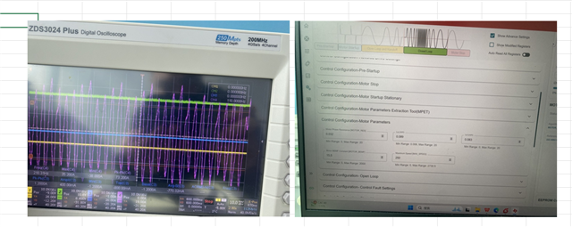
The customer designed the BLDC circuit using MCF8329A, using NXP's MCU and communicating with MCF8329A IC through I2C. The first few frames of I2C data are normal, but after a few frames of data, 8329A will actively pull down the I2C bus What causes this phenomenon (removing 8329A, I2C signal returns to normal)? Is it necessary to have a delay of about 100us between I2C frames as suggested in the 8329A specification? In addition, when we tested 8329AEVM, we found that the phase current ran to around 20A, and the motor could not operate stably. The motor parameters are shown in the attached figure. 8329A configuration parameters are attached. What could be the cause of this?Thank you!

{
"signature":"oneui-register-data",
"data":[
[
{
"idx":0,
"id":"ISD_CONFIG",
"value":"0x4462AC20",
"addr":"0x00000080"
},
{
"idx":1,
"id":"REV_DRIVE_CONFIG",
"value":"0xA8200000",
"addr":"0x00000082"
},
{
"idx":2,
"id":"MOTOR_STARTUP1",
"value":"0x088748D0",
"addr":"0x00000084"
},
{
"idx":3,
"id":"MOTOR_STARTUP2",
"value":"0x8B11C094",
"addr":"0x00000086"
},
{
"idx":4,
"id":"CLOSED_LOOP1",
"value":"0x0C3101B8",
"addr":"0x00000088"
},
{
"idx":5,
"id":"CLOSED_LOOP2",
"value":"0x8BAD1530",
"addr":"0x0000008A"
},
{
"idx":6,
"id":"CLOSED_LOOP3",
"value":"0x214C9E40",
"addr":"0x0000008C"
},
{
"idx":7,
"id":"CLOSED_LOOP4",
"value":"0x641E05DC",
"addr":"0x0000008E"
},
{
"idx":8,
"id":"REF_PROFILES1",
"value":"0x00000000",
"addr":"0x00000094"
},
{
"idx":9,
"id":"REF_PROFILES2",
"value":"0x00000000",
"addr":"0x00000096"
},
{
"idx":10,
"id":"REF_PROFILES3",
"value":"0x00000000",
"addr":"0x00000098"
},
{
"idx":11,
"id":"REF_PROFILES4",
"value":"0x800D0000",
"addr":"0x0000009A"
},
{
"idx":12,
"id":"REF_PROFILES5",
"value":"0x00000000",
"addr":"0x0000009C"
},
{
"idx":13,
"id":"REF_PROFILES6",
"value":"0x00000000",
"addr":"0x0000009E"
}
],
[
{
"idx":0,
"id":"FAULT_CONFIG1",
"value":"0xBED27126",
"addr":"0x00000090"
},
{
"idx":1,
"id":"FAULT_CONFIG2",
"value":"0xF7C27CB9",
"addr":"0x00000092"
}
],
[
{
"idx":0,
"id":"INT_ALGO_1",
"value":"0xA2B3417D",
"addr":"0x000000A0"
},
{
"idx":1,
"id":"INT_ALGO_2",
"value":"0x000002A7",
"addr":"0x000000A2"
}
],
[
{
"idx":0,
"id":"PIN_CONFIG",
"value":"0x0000000A",
"addr":"0x000000A4"
},
{
"idx":1,
"id":"DEVICE_CONFIG1",
"value":"0x00101461",
"addr":"0x000000A6"
},
{
"idx":2,
"id":"DEVICE_CONFIG2",
"value":"0x03E8D00C",
"addr":"0x000000A8"
},
{
"idx":3,
"id":"PERI_CONFIG1",
"value":"0x340E9CC1",
"addr":"0x000000AA"
},
{
"idx":4,
"id":"GD_CONFIG1",
"value":"0x9C45017A",
"addr":"0x000000AC"
},
{
"idx":5,
"id":"GD_CONFIG2",
"value":"0x00000800",
"addr":"0x000000AE"
}
],
[
{
"idx":0,
"id":"GATE_DRIVER_FAULT_STATUS",
"value":"0x00000000",
"addr":"0x000000E0"
},
{
"idx":1,
"id":"CONTROLLER_FAULT_STATUS",
"value":"0x00000000",
"addr":"0x000000E2"
}
],
[
{
"idx":0,
"id":"ALGO_STATUS",
"value":"0x0A3C6E14",
"addr":"0x000000E4"
},
{
"idx":1,
"id":"MTR_PARAMS",
"value":"0x00000000",
"addr":"0x000000E6"
},
{
"idx":2,
"id":"ALGO_STATUS_MPET",
"value":"0x0A000000",
"addr":"0x000000E8"
}
],
[
{
"idx":0,
"id":"ALGO_CTRL1",
"value":"0x20000000",
"addr":"0x000000EA"
}
],
[
{
"idx":0,
"id":"ALGO_DEBUG1",
"value":"0xE3D60000",
"addr":"0x000000EC"
},
{
"idx":1,
"id":"ALGO_DEBUG2",
"value":"0x00000018",
"addr":"0x000000EE"
},
{
"idx":2,
"id":"CURRENT_PI",
"value":"0x03400321",
"addr":"0x000000F0"
},
{
"idx":3,
"id":"SPEED_PI",
"value":"0x013D003D",
"addr":"0x000000F2"
},
{
"idx":4,
"id":"DAC_1",
"value":"0x00000000",
"addr":"0x000000F4"
}
],
[
{
"idx":0,
"id":"ALGORITHM_STATE",
"value":"0x00200008",
"addr":"0x00000196"
},
{
"idx":1,
"id":"FG_SPEED_FDBK",
"value":"0x7FFFFFFF",
"addr":"0x0000019C"
},
{
"idx":2,
"id":"BUS_CURRENT",
"value":"0x00000000",
"addr":"0x0000040E"
},
{
"idx":3,
"id":"PHASE_CURRENT_A",
"value":"0xFFF20000",
"addr":"0x0000043C"
},
{
"idx":4,
"id":"PHASE_CURRENT_B",
"value":"0xFD300000",
"addr":"0x0000043E"
},
{
"idx":5,
"id":"PHASE_CURRENT_C",
"value":"0x02C60000",
"addr":"0x00000440"
},
{
"idx":6,
"id":"CSA_GAIN_FEEDBACK",
"value":"0x00000001",
"addr":"0x00000450"
},
{
"idx":7,
"id":"VOLTAGE_GAIN_FEEDBACK",
"value":"0x00000001",
"addr":"0x00000458"
},
{
"idx":8,
"id":"VM_VOLTAGE",
"value":"0x01D05010",
"addr":"0x0000045C"
},
{
"idx":9,
"id":"PHASE_VOLTAGE_VA",
"value":"0x02A0E6D7",
"addr":"0x00000460"
},
{
"idx":10,
"id":"PHASE_VOLTAGE_VB",
"value":"0x02A0E6D7",
"addr":"0x00000462"
},
{
"idx":11,
"id":"PHASE_VOLTAGE_VC",
"value":"0x02A00923",
"addr":"0x00000464"
},
{
"idx":12,
"id":"SIN_COMMUTATION_ANGLE",
"value":"0x00000000",
"addr":"0x000004AA"
},
{
"idx":13,
"id":"COS_COMMUTATION_ANGLE",
"value":"0x08000000",
"addr":"0x000004AC"
},
{
"idx":14,
"id":"IALPHA",
"value":"0x00060000",
"addr":"0x000004CC"
},
{
"idx":15,
"id":"IBETA",
"value":"0xFCBD26CA",
"addr":"0x000004CE"
},
{
"idx":16,
"id":"VALPHA",
"value":"0xFFFF61F2",
"addr":"0x000004D0"
},
{
"idx":17,
"id":"VBETA",
"value":"0xFFDAEF87",
"addr":"0x000004D2"
},
{
"idx":18,
"id":"ID",
"value":"0x000A0000",
"addr":"0x000004DC"
},
{
"idx":19,
"id":"IQ",
"value":"0xFCCD513C",
"addr":"0x000004DE"
},
{
"idx":20,
"id":"VD",
"value":"0xFFFF6494",
"addr":"0x000004E0"
},
{
"idx":21,
"id":"VQ",
"value":"0xFFDAFBB9",
"addr":"0x000004E2"
},
{
"idx":22,
"id":"IQ_REF_ROTOR_ALIGN",
"value":"0xFCCCD8E0",
"addr":"0x0000051A"
},
{
"idx":23,
"id":"SPEED_REF_OPEN_LOOP",
"value":"0x00000000",
"addr":"0x00000532"
},
{
"idx":24,
"id":"IQ_REF_OPEN_LOOP",
"value":"0x00000000",
"addr":"0x00000542"
},
{
"idx":25,
"id":"SPEED_REF_CLOSED_LOOP",
"value":"0x01495113",
"addr":"0x000005D0"
},
{
"idx":26,
"id":"ID_REF_CLOSED_LOOP",
"value":"0x00000000",
"addr":"0x0000060A"
},
{
"idx":27,
"id":"IQ_REF_CLOSED_LOOP",
"value":"0x00000000",
"addr":"0x0000060C"
},
{
"idx":28,
"id":"ISD_STATE",
"value":"0x00000000",
"addr":"0x000006B0"
},
{
"idx":29,
"id":"ISD_SPEED",
"value":"0x00000000",
"addr":"0x000006BA"
},
{
"idx":30,
"id":"IPD_STATE",
"value":"0x00000000",
"addr":"0x000006E4"
},
{
"idx":31,
"id":"IPD_ANGLE",
"value":"0x00000000",
"addr":"0x0000071A"
},
{
"idx":32,
"id":"ED",
"value":"0x00000000",
"addr":"0x0000075C"
},
{
"idx":33,
"id":"EQ",
"value":"0x00000000",
"addr":"0x0000075E"
},
{
"idx":34,
"id":"SPEED_FDBK",
"value":"0x01656BEB",
"addr":"0x0000076E"
},
{
"idx":35,
"id":"THETA_EST",
"value":"0x00554DEB",
"addr":"0x00000774"
}
]
]
}

  • Hi Eric,

    Thanks for reaching out. 

    The first few frames of I2C data are normal, but after a few frames of data, 8329A will actively pull down the I2C bus What causes this phenomenon (removing 8329A, I2C signal returns to normal)?

    Regarding above query, it is an expected phenomenon. The MCx portfolio of devices have "Clock Streching" which is essentially a feature in the device where the bus is held low for some time (maximum is about 5ms) to enable time for data fetching and processing. Please make sure the primary device (MPS) here, supports clock streching.

    In addition, when we tested 8329AEVM, we found that the phase current ran to around 20A, and the motor could not operate stably. The motor parameters are shown in the attached figure. 8329A configuration parameters are attached. What could be the cause of this?Thank you!

    Regarding your second question, could you please run the motor in Current Control mode and let me know how if the waveform improves? This is to understand if the problem is in current loop or speed loop 

    Regards,
    Sachin S

  • Sachin

    The modification to the current control mode still has an abnormality, and the phenomenon is consistent.

  • Hi,

    Looks like the current loop is not functioning well.

    There are two control loops in the device - 1. Speed Control 2. Current Control. Speed control always runs current control as current control is an inner loop functioning within the speed loop. So since the current loop is instable, please try to tune out the current loop using the method from the guide attached.

    Current Loop Kp Ki tuning with MOTORSTUDIO.pdf

    Thanks and regards,

    Sachin S

  • Hello, I can also change the sampling blanking time to make the control better, please help to confirm if there are other points that can optimize the sampling related issues. This question is urgent, please help reply, or please tell us how to confirm that there is no problem with current sampling, and if there is any relevant documentation, please give it.

  • Also, I don't do this for the whole rev range, I'm just full speed, which happens when I don't reach the target speed. That's a problem。

  • Hi,

    You can also tune the PWM frequency (suggested to set it at 25/30kHz). You can also set the MCC_DEAD_TIME to around 200ns.

    Thanks and regards,

    Sachin S

  • It is effective to reduce the dead time, but in the actual application of products, in order to meet the hardware design risk, the dead time will not be set so small. I can't force it to be so small, is there any other way to optimize this point, and if not, how should I adjust the application of this chip.

  • Hi Zhang,

    Could you also verify if the motor parameters are entered correctly? We need per phase quantities (not phase-to-phase). Also, how are you measuring the resistance of the motor? 

    Thanks and regards,

    Sachin S

  • I'm now testing relative to the value of the phases, is this way abnormal? If it's abnormal, how should I measure it and help show the intent.

  • About I2C communication failures,What is the manifestation of this clock streching error Is the clock pulling down?
    The situation where we are experiencing bus failures now is that the SCL clock is pulled up and the SDA data is pulled low.

  • About I2C communication failures,What is the manifestation of this clock streching error Is the clock pulling down?
    The situation where we are experiencing bus failures now is that the SCL clock is pulled up and the SDA data is pulled low.

  • Hi Zhang,

    Sachin is out of office today he will continue discussion from tomorrow.

    Clock stretch is pulling clock low. In this case SDA is low means there can be missing clock, you can try pulsing a clock (toggle the SCL line) to release SDA.

    While data transmission in progress when SDA is low, if a clock is missing then SDA will remain low waiting for I2C frame to complete.

     Thanks and Best Regards

    Venkatadri S

  • For example, when the SDA line is pulled low, and the SCL is high or low for a long time, can I directly use the host to reverse the SCL? Is it enough to end the data in this frame?

  • Hi Zhang,

    Try from first toggle, we don't know which clock count is missed.

    Thanks and Best Regards 

    Venkatadri S 

  • The first time means that when the clock is missing, and the SDA data line is pulled down, I start to change the level polarity of the SCL until the SDA data line data is pulled up, right? Is this line of thinking correct?

  • For a debugging scheme similar to a current loop, whether it is convenient to provide a debugging manual for debugging such as ISD, or if there is a website dedicated to introducing relevant debugging skills, please help to share.

  • In addition, when I am using the MCF8329EVM development board, the MSP430 chip is damaged, is there any way to fix it? Or I bought a chip to replace, whether I can provide the program of 430 in the EVM to me, I am very distressed, because whether the EVM debugging verification is successful is related to our company's 20K mass production procurement plan.

  • Hello Zhang, 

    I am back in office. Will take the e2e from here. I will look at the details and respond by 15-Mar.

    Thanks and regards,

    Sachin S

  • Okay, thanks, be sure to reply quickly and in detail, thanks thanks

  • I am currently using other chips to control 8329A, is there a routine, such as how to convert the collected voltage value and other examples, please help provide.

  • Hello Zhang, 

    The first time means that when the clock is missing, and the SDA data line is pulled down, I start to change the level polarity of the SCL until the SDA data line data is pulled up, right? Is this line of thinking correct?

    Yes, you can toggle the SCL to give one clock pulse and verify if the bus becomes active again. Please share waveforms if possible.

    For a debugging scheme similar to a current loop, whether it is convenient to provide a debugging manual for debugging such as ISD, or if there is a website dedicated to introducing relevant debugging skills, please help to share.

    We are publishing a document for ISD soon (by next week) will update you.

    In addition, when I am using the MCF8329EVM development board, the MSP430 chip is damaged, is there any way to fix it? Or I bought a chip to replace, whether I can provide the program of 430 in the EVM to me, I am very distressed, because whether the EVM debugging verification is successful is related to our company's 20K mass production procurement plan.

    You can replace the MSP chip and load the firmware for MOTORSTUDIO by following the instructions from this E2E FAQ. I understand this is an important project for you. Please don't worry, we will provide support to you with solutions for your problems. Most of the problems here should be fixable.

    I am currently using other chips to control 8329A, is there a routine, such as how to convert the collected voltage value and other examples, please help provide.

    Could you add more details here? What do you mean by "collected voltage"?

    Thanks and regards,

    Sachin S

  • Sachin S:Could you add more details here? What do you mean by "collected voltage"?

    Meaning, I get the voltage register value of the monitor from the I2C communication, how to convert it to the real voltage value, current value, etc., is there a programming case, I have some anomalies in the formula conversion from the datasheet. I need a case, a case where the code can be reproduced.

  • MSP430 LaunchPad,I don't have this tool, and my current 8329EVM doesn't have D6 and D7 chips, please help confirm. Is there any other way to program the 430 firmware. Using any 430 programmer, download the 8329A program from the official website and use the CCS development environment to compile and burn it.

  • You can replace the MSP chip and load the firmware for MOTORSTUDIO by following the instructions from this E2E FAQ. I understand this is an important project for you. Please don't worry, we will provide support to you with solutions for your problems. Most of the problems here should be fixable.

    MSP430 LaunchPad,I don't have this tool, and my current 8329EVM doesn't have D6 and D7 chips, please help confirm. Is there any other way to program the 430 firmware. Using any 430 programmer, download the 8329A program from the official website and use the CCS development environment to compile and burn it.

  • You can replace the MSP chip and load the firmware for MOTORSTUDIO by following the instructions from this E2E FAQ. I understand this is an important project for you. Please don't worry, we will provide support to you with solutions for your problems. Most of the problems here should be fixable.

    Currently after I install the new 430, there is no LED on. Recently, I re-ordered the EVM, can you send some 430 firmware that has been burned to solve my problem.

  • Hi Zhang,

    Could you check this E2E FAQ link as mentioned in my response. You may need to order another MSP board to enable burning the program into the new MSP.

    Regards,

    Sachin S

  • Hi Zhang, 

    Currently after I install the new 430, there is no LED on. Recently, I re-ordered the EVM, can you send some 430 firmware that has been burned to solve my proble

    Sorry I did not look at your previous responses. Would it be possible to order the MSP430 Launch Pad? If not let me know. 

    Regards,

    Sachin S

  • Hi,Sachin ,Excuse me, when we use the 8329A chip to convert the current register reading to the true value, according to the description of the specification, we need to divide it by about 27 on the basis of the formula (IBus = (BUS_CURRENT/227) * Base_Current/(2CSA_GAIN_FEEDBACK)) to be the true value, why? I've also verified it on the 8329EVM, and the real feedback is about 27% different from the contents of the register (offset = 40Eh).

  • Hello Zhang,

    Could you share the measured values (real feedback) and the readback values (register value). How are you measuring the real DC bus current?

    Thanks and regards,

    Sachin S

  • BUS_CURRENT:0x7007aab;CSA_GAIN : 10V/V;     BASE_CURRENT:0X556。    The real power bus uses a current clamp test value of 11A, which is 27 times different from the current value calculated using the above parameter formula.

  • Hi Zhang,

    Could you confirm if the BASE_CURRENT value is correct, I am not getting anywhere close to 11A with the above values.

    What is the calculated value you are getting?

    Also, if the earlier questions are resolved, do you mind starting a new thread? This helps others to find related questions easily.

    Regards,

    Sachin S

  • idx id value addr
    0 ISD_CONFIG 0x006CAC20 0x00000080
    1 REV_DRIVE_CONFIG 0xA8200000 0x00000082
    2 MOTOR_STARTUP1 0x048748D0 0x00000084
    3 MOTOR_STARTUP2 0x8B11C294 0x00000086
    4 CLOSED_LOOP1 0x143181B8 0x00000088
    5 CLOSED_LOOP2 0x8BAD1530 0x0000008A
    6 CLOSED_LOOP3 0x216658A2 0x0000008C
    7 CLOSED_LOOP4 0x64590640 0x0000008E
    8 REF_PROFILES1 0x0604A6A0 0x00000094
    9 REF_PROFILES2 0x05000000 0x00000096
    10 REF_PROFILES3 0x00000000 0x00000098
    11 REF_PROFILES4 0x800D0000 0x0000009A
    12 REF_PROFILES5 0x00000000 0x0000009C
    13 REF_PROFILES6 0x00000000 0x0000009E
    0 FAULT_CONFIG1 0xC6EA71A6 0x00000090
    1 FAULT_CONFIG2 0xF7C27CB9 0x00000092
    0 INT_ALGO_1 0xA2B3417D 0x000000A0
    1 INT_ALGO_2 0x000002A7 0x000000A2
    0 PIN_CONFIG 0x00000009 0x000000A4
    1 DEVICE_CONFIG1 0x00101461 0x000000A6
    2 DEVICE_CONFIG2 0x03E8D00C 0x000000A8
    3 PERI_CONFIG1 0x3F0E9EC1 0x000000AA
    4 GD_CONFIG1 0x9C450179 0x000000AC
    5 GD_CONFIG2 0x00000556 0x000000AE
  • The parameters are shown in the following table, which is correct, the current sampling resistance is 0.003Ω, which is obtained according to 1.5/(0.003*10)*32767/1200.

  • Ok please give me a day to look into this. Will respond by tomorrow,

    Regards,

    Sachin S

  • 1. Now the application of 8329A, the power limit wants to be very accurate, is there a solution, now the minimum spacing of 5% can not meet my requirements, 2, I also want to consult if I want to do the function of the three-phase motor missing one phase, how to make this, how to solve the solution

  • Hi Zhang,

    Now the application of 8329A, the power limit wants to be very accurate, is there a solution, now the minimum spacing of 5% can not meet my requirements

    Do you mean the power limit accuracy requirement is 5%? 

    I also want to consult if I want to do the function of the three-phase motor missing one phase, how to make this, how to solve the solution

    The device has a NO_MTR detection feature, which can be used to detect a missing phase.

    Regards,

    Sachin S

  • I need a current limiting accuracy of 1% of the maximum current.

  • Hi Zhang,  

    Sachin is out of office today and will respond to the questions tomorrow.

    Regards,

    Manu

  • Hi Zhang, 

    I think we can get an accurate current control and achieve 1% if that is what you are asking. Could you please start a new thread? We have discussed a lot of questions here, it would help others to find and understand similar problems if we create new threads for new discussions.

    Thanks and regards,

    Sachin S

  • Please assist in re-establishing a discussion thread for a question regarding how to achieve 1% accuracy in current limiting, based on the aforementioned motor configuration.

  • Hello Zhang,

    You can click on "Ask a related question" on the top of the page. 

    Could you please provide more details on the the 1% accuracy? Are you looking to control the current limit at 1% accuracy (in closed loop current mode)? 

    Regards,
    Sachin S