This thread has been locked.

If you have a related question, please click the "Ask a related question" button in the top right corner. The newly created question will be automatically linked to this question.

DRV8818: low current issue of bridge A

Part Number: DRV8818
Other Parts Discussed in Thread: DRV8434, DRV8825, DRV8424

Tool/software:

Hi Team,

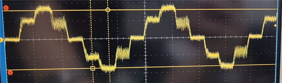
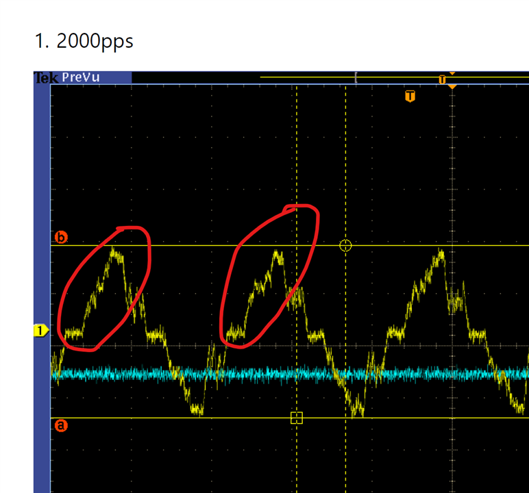
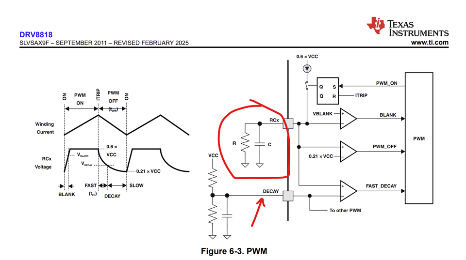
There is low current issue of bridge A on customer's board with DRV8818. They are verifying DRV8818 under condition of 1000pps to 5500pps, but the current of bridge A is decreasing after about 3500~4000pps. Please check the schematic and video clip of attachment below, and let me know how to resolve this issue.

Low current issue of bridge A.docx

Regards,

  • Hi Jeffrey,

    Thanks for reaching out to us via this forum. Thanks for the detailed video clip of the current waveform behavior at various pps speed settings. Current amplitude reduction with higher speeds is a classical behavior of stepper motors. It is not due to the driver. At higher speeds the BEMF voltage increases and opposes the VM voltage 24 V in this case. As a result the coils cannot achieve the target current for Itrip regulation after a certain speed and then it gets lower and lower resulting in reduced torque output and eventually stalling the motor.

    Potential solution for this scenario are 1) Increase VM voltage for example up to 33 V with the DRV8818 or 48 V and use drivers such as the DRV8434. 2) Reduce the VREF to reduce the target Itrip which can provide better waveform up to a certain speed but overall reduced torque that may be okay for the application or 3) Use a stepper motor with lower BEMF constant, lower DCR. Thank you.

    Regards, Murugavel 

  • Hi Murugavel,

    Thank you for kind response. Let me check it with customer.

    Regards,

  • Hi Murugavel,

    There are two more questions below about this issue from customer. Please check it and let me know.

    1. They are tying to use a schottky diode on the output of motor driver for the improvement of BEMF. Is it good idea or not? If not, please let me know the better idea.

    2. They set the winding current of 2A through VREF, but the peak current input to the motor is about 1.75A. Could you explain about this?

    Regards,

  • Hi Jeffrey,

    1. They are tying to use a schottky diode on the output of motor driver for the improvement of BEMF. Is it good idea or not? If not, please let me know the better idea.

    I assume four Schottky diodes were used one across each output FET (parallel to its body diode). This will help reduce the inductive kickback during switching both VM + diode drop and - diode drop will get lower. I don't expect this to change the BEMF. BEMF depends on motor rotation only and motor internal parameters. Also reduce the strain on the body diodes. While external diodes are not necessary it would not affect anything negatively.

    2. They set the winding current of 2A through VREF, but the peak current input to the motor is about 1.75A. Could you explain about this?

    Did you mean the current at lower speed is < the set Itrip? I see current regulation happening at the peaks. So it should follow the VREF to IFS formula in the datasheet. Please measure the VREF and see exact value of its voltage. At higher speeds the current is reduced due to increased BEMF and 24 V not enough to push the current to the peak level due to time constant of the stepper. Thank you.

    Regards, Murugavel 

  • Hi Murugavel,

    Customer tested again by your comment. They set the current of 2.185A through VREF(3.5V), but the peak current value is not matched under condition of 2000pps, 3000pps, and 4000pps. Please check the attachment below and let me know how to improve it.

    Vref and current waveform of bridge A.pdf

    Regards,

  • Hi Jeffrey,

    These waveforms suggest the VM 24 V is not high enough to push the current to the desired level in the short period of time (high pps and microsteps) due to the BEMF voltage. I mentioned this previously. What is the L and R of the stepper motor? Can we get its datasheet?

    Regards, Murugavel 

  • Hi Murugavel,

    Please check the specification of stepper motor below and let me know how to improve the BEMF voltage under condition of 2000pps to 3000pps.

    Specification of Stepper Motor.pdf

    Regards,

  • Hi Jeffrey,

    The L/R time constant of the stepper is (3.6 / 1.4) ms = ~ 2.6 ms. Available time at 2000 pps is 0.5 ms, and at 3000 pps is 0.333 ms. which are significantly less than the time constant of the stepper hence the current distortion at these speeds. A higher resistance stepper with same inductance would reduce the time constant -or- a lower inductance stepper would be better. 

    If the motor is generating enough torque and running fine with load distorted current waveform will not be an issue except for reduced torque. Many stepper applications have distorted waveforms at higher speeds, for example printer CR movement. 

    Regards, Murugavel  

  • Hi Murugavel,

    Thank you for your kind response.

    Customer changed the driver to DRV8825, but their low current issue of high speed has been resolved at same test condition. So they are trying to change it to DRV8825 instead of DRV8818. Could you explain about this?

    Regards,

  • Hi Jeffrey,

    If the customer is willing to change the driver IC I'd recommend a newer design driver such as the DRV8424 or the DRV8434. These new drivers use smart tune decay which supports higher microsteps smoothly and with low audible noise from the motor. 

    So they are trying to change it to DRV8825 instead of DRV8818. Could you explain about this?

    It is likely the decay configurations were not matching the motor operation at higher speeds. They may have tweak it to see if it improves. Also tweaking TOFF by RC should help improve.

    Regards, Murugavel